US6169394B1 - Electrical detector for micro-analysis systems - Google Patents
Electrical detector for micro-analysis systems Download PDFInfo
- Publication number
- US6169394B1 US6169394B1 US09/154,668 US15466898A US6169394B1 US 6169394 B1 US6169394 B1 US 6169394B1 US 15466898 A US15466898 A US 15466898A US 6169394 B1 US6169394 B1 US 6169394B1
- Authority
- US
- United States
- Prior art keywords
- microchannel
- detector
- substrate
- sensor device
- electrodes
- Prior art date
- Legal status (The legal status is an assumption and is not a legal conclusion. Google has not performed a legal analysis and makes no representation as to the accuracy of the status listed.)
- Expired - Lifetime
Links
Images


Classifications
-
- G—PHYSICS
- G01—MEASURING; TESTING
- G01N—INVESTIGATING OR ANALYSING MATERIALS BY DETERMINING THEIR CHEMICAL OR PHYSICAL PROPERTIES
- G01N30/00—Investigating or analysing materials by separation into components using adsorption, absorption or similar phenomena or using ion-exchange, e.g. chromatography or field flow fractionation
- G01N30/02—Column chromatography
- G01N30/62—Detectors specially adapted therefor
- G01N30/64—Electrical detectors
-
- G—PHYSICS
- G01—MEASURING; TESTING
- G01N—INVESTIGATING OR ANALYSING MATERIALS BY DETERMINING THEIR CHEMICAL OR PHYSICAL PROPERTIES
- G01N27/00—Investigating or analysing materials by the use of electric, electrochemical, or magnetic means
- G01N27/26—Investigating or analysing materials by the use of electric, electrochemical, or magnetic means by investigating electrochemical variables; by using electrolysis or electrophoresis
- G01N27/416—Systems
- G01N27/447—Systems using electrophoresis
- G01N27/44704—Details; Accessories
- G01N27/44717—Arrangements for investigating the separated zones, e.g. localising zones
- G01N27/4473—Arrangements for investigating the separated zones, e.g. localising zones by electric means
-
- G—PHYSICS
- G01—MEASURING; TESTING
- G01N—INVESTIGATING OR ANALYSING MATERIALS BY DETERMINING THEIR CHEMICAL OR PHYSICAL PROPERTIES
- G01N27/00—Investigating or analysing materials by the use of electric, electrochemical, or magnetic means
- G01N27/26—Investigating or analysing materials by the use of electric, electrochemical, or magnetic means by investigating electrochemical variables; by using electrolysis or electrophoresis
- G01N27/416—Systems
- G01N27/447—Systems using electrophoresis
- G01N27/44756—Apparatus specially adapted therefor
- G01N27/44791—Microapparatus
-
- G—PHYSICS
- G01—MEASURING; TESTING
- G01N—INVESTIGATING OR ANALYSING MATERIALS BY DETERMINING THEIR CHEMICAL OR PHYSICAL PROPERTIES
- G01N15/00—Investigating characteristics of particles; Investigating permeability, pore-volume, or surface-area of porous materials
- G01N15/10—Investigating individual particles
- G01N15/14—Electro-optical investigation, e.g. flow cytometers
-
- G—PHYSICS
- G01—MEASURING; TESTING
- G01N—INVESTIGATING OR ANALYSING MATERIALS BY DETERMINING THEIR CHEMICAL OR PHYSICAL PROPERTIES
- G01N30/00—Investigating or analysing materials by separation into components using adsorption, absorption or similar phenomena or using ion-exchange, e.g. chromatography or field flow fractionation
- G01N30/0005—Field flow fractionation
-
- G—PHYSICS
- G01—MEASURING; TESTING
- G01N—INVESTIGATING OR ANALYSING MATERIALS BY DETERMINING THEIR CHEMICAL OR PHYSICAL PROPERTIES
- G01N30/00—Investigating or analysing materials by separation into components using adsorption, absorption or similar phenomena or using ion-exchange, e.g. chromatography or field flow fractionation
- G01N30/02—Column chromatography
- G01N30/60—Construction of the column
- G01N30/6095—Micromachined or nanomachined, e.g. micro- or nanosize
Definitions
- the present invention relates generally to detector systems for measurement of the electrical characteristics of liquids, gases and biological materials. More specifically, the present invention relates to an electrical detector for micro-analysis systems capable of providing conductivity or impedance based measurements on a microscale of particulates in liquids or gases, and biological materials such as living cells.
- DP and ER Dielectrophoresis and electrorotation (ER) are relatively well established techniques for studying dielectric properties such as membrane capacitance and conductance, as well as cytoplasmic permittivity, of individual isolated cells.
- the DP and ER techniques measure the net force and torque which are generated when the substance of interest is placed in a nonuniform electric field.
- the required information namely the polarization vector
- the actual electric field is dependent upon the geometry and the materials involved, and can be interpreted to some extent though the use of the measured data along with the appropriate electromagnetic model.
- micro-ER device has been developed in which four gold electrodes are electroplated and oriented orthogonally on a glass wafer to create a recording zone on the surface of the wafer. Gimsa et al., Biophysical Journal, vol. 71, p. 495-506 (1996). Although this micro-ER device is capable of somewhat smaller spatial resolution, the device still suffers from the aforementioned difficulties generally associated with ER systems, and in addition, fails to resolve electrical characteristics on a subcellular level.
- Electric impedance measurements have previously been demonstrated as an effective technique to characterize dielectric properties of tissues or cell suspensions.
- the electric impedance of tissues and cells is of interest in part because the impedance is known to vary with the morphology, histopathology, and electrophysiology of certain cells, and can therefore be used to monitor or detect certain pathological conditions or changes in the cells.
- Prior electric impedance measurement systems for cell layers and tissues have been developed.
- an impedance sensing system has been developed which performs impedance spectroscopy, i.e., impedance variations in tissue and cell layers measured as a function of applied alternating currents (AC), typically in the range of 20 to 50,000 Hz.
- AC applied alternating currents
- the sensing system was fabricated by sputtering gold onto thin polycarbonate sheets, and photolithography was used to delineate the desired gold patterns on the thin sheets and form the active electrode pairs.
- the Lo system is usefull in providing additional information on the resistive and capacititve properties of cells and cell membranes, the system fails to resolve electrical characteristics on a subcellular level.
- optical techniques generally used with chromatography systems have several disadvantages. They are generally very bulky, expensive, complex, and often require modification of the sample being detected in order to perform measurements. These optical techniques are also very sensitive to physical movement and require considerable maintenance. While the UV extinction and light scattering techniques are quite robust and allow for a wide variety of sample types, they are also expensive and bulky. For large-scale labs with fixed laboratory equipment, these detection techniques provide high sensitivity and are well characterized and developed, but are not suitable for use with portable equipment, and especially for use with the new generation of microscale analysis systems.
- micromachined systems rely on off-chip components to perform the bulk of the detection and signal processing functions. These detection systems are generally the same as those used for the corresponding macro-analysis system with slight modifications for working on the smaller microscale systems. In many cases, after processing the sample using the microscale device, the sample is moved off chip for analysis. Moving the sample off-chip, though, can be very detrimental in terms of resolution for chromatography systems, and measurement quality for other systems.
- a further object of the invention is to provide a conductivity or impedance detector device for particles which have been separated by micro-analysis systems which achieves a higher performance (e.g., increased resolution, decreased band broadening, etc.) than conventional off-chip detectors.
- a micro-electric detector for conductivity or impedance based measurements of a test sample placed in a microchannel of a micro-analysis system.
- the detector includes a pair of electrodes disposed on opposing sidewalls of the microchannel to create a detection zone in the microchannel between and adjacent to the electrodes.
- the detector can be utilized in a variety of micro-analysis systems such as micro-electric-impedance systems which utilize micro-electric sensors, electrical field-flow fractionation systems, chromatography systems, and the like.
- the detector is integrated on-chip with the micro-analysis system by micromachining techniques.
- a micro-electric sensor device with an on-chip detector for use in a micro-analysis system includes a substrate having a substantially planar upper surface. At least one microchannel is formed in the upper surface of the substrate and is defined by a pair of opposing sidewalls and a bottom wall in the substrate. One or more reservoirs are formed in the planar surface of the substrate and are in fluid communication with the microchannel. At least one pair of opposing detector electrodes are formed on the planar surface of the substrate and terminate at electrode tips formed on the opposing sidewalls of the microchannel such that the electrode tips face each other. This creates a detection zone in the microchannel between and adjacent to the electrodes such that the electrodes provide for transverse interrogation of a test sample in the microchannel by conductivity or impedance based measurements.
- a micromachined system for electrical field-flow fractionation ( ⁇ -EFFF) of a fluid incorporates a detector on-chip according the present invention.
- the ⁇ -EFFF system includes a microchannel device comprising a first substrate having a planar inner surface with an electrically conductive layer such as an electrode formed thereon.
- the system also includes a second substrate having a planar inner surface with an electrically conductive layer such as an electrode formed thereon.
- the second substrate is positioned over the first substrate so that the respective conductive layers of the first and second substrates face each other.
- An intermediate layer such as an insulating layer is interposed between the first and second substrates, with the intermediate layer being patterned to form opposing sidewalls of at least one microchannel.
- the conductive layers on the first and second substrates define opposing boundaries along the length of the microchannel.
- Inlet and outlet ports are formed in the first and/or second substrate to allow fluid flow into and out of the microchannel.
- a detector comprising at least one pair of opposing electrodes is formed on the inner surfaces of the first and second substrates adjacent to the outlet port. This creates a detection zone in the microchannel between and adjacent to the electrodes such that the detector can provide conductivity or impedance based measurements of a fluid sample in the microchannel.
- a method for monitoring a test sample in a micro-analysis system includes providing a device with at least one microchannel and an associated detector electrode pair in the microchannel, and supplying electrical power to the electrodes to create an electric field in the detection zone of the microchannel between and adjacent to the electrodes.
- a test sample is injected into the microchannel and changes in the electric field are detected as the test sample enters the detection zone of the microchannel to provide conductivity or impedance based measurements of the test sample.
- test samples can be monitored by the detector of the invention, such as particulate-containing fluids and biological materials including living cells and subcellular structures.
- the detector provides for subcellular spatial resolution in biological systems, and can be used to characterize the dielectric properties of a small sample of material or measure the concentration of particles which have been separated by a biological or chemical micro-analysis system.
- FIG. 1 is a schematic depiction of a detection system according to the present invention
- FIG. 2A is a schematic plan view of a micro-electric-impedance sensor device according to one embodiment which incorporates the detector of the invention
- FIG. 2B is an enlarged sectional view of the sensor device of FIG. 2A;
- FIG. 3A is a schematic plan view of a micro-electric-impedance sensor device according to another embodiment which incorporates the detector of the invention.
- FIG. 3B is an enlarged sectional view of the sensor device of FIG. 3A;
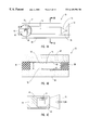
- FIG. 4A is a schematic depiction of a microchannel device for a ⁇ -EFFF system which incorporates the detector of the invention
- FIG. 4B is a schematic cross-sectional view perpendicular to fluid flow of the microchannel device of FIG. 4A;
- FIG. 4C is an enlarged sectional view of the microchannel device of FIG. 4A;
- FIGS. 5 A- 5 F are graphs showing the results of electric impedance measurements for a range of frequencies with a micro-electric-impedance sensor device of the invention.
- FIGS. 6A and 6B are graphs of the measured current as a function of time for an impedance detector of the invention.
- FIG. 7 is a graph of the time constants necessary to reach steady state for a series of flow rates and voltages for the detector of the invention.
- FIG. 8 is a graph showing superimposed data for sample runs at a variety of voltages for a detector of the invention.
- FIG. 9 is a graph showing the maximum signal obtained for sample runs with only a variation in voltage
- FIG. 10 is a graph showing superimposed data for signals measured by a detector of the invention for a variety of sample concentrations
- FIG. 11 is a graph showing how the signal measured by the detector of the invention varies with sample concentration
- FIG. 12 is a graph showing several superimposed signals demonstrating how variations in flow rate affect the signal generated by the detector of the invention.
- FIG. 13 is a graph of the effective plate heights as a function of flow rate for an off-chip detection system
- FIG. 14 is a graph of the effective plate heights as a function of flow rate for an on-chip detection system of the invention and an off-chip detection system;
- FIG. 15 is a graph of the detector response as a function of time for an off-chip detection system.
- FIG. 16 is a graph of the detector response as a function of time for an on-chip detection system of the invention.
- the present invention is directed to a low power micro-electric detector which can be utilized in a variety of micro-analysis systems.
- the detector can provide conductivity or impedance based measurements of a test sample placed in a microchannel of a micro-analysis system.
- the detector can be integrated on-chip to provide a conductivity or impedance based detection system for miniaturized biochemical analysis systems such as liquid chromatography systems, micro-electric-impedance systems which utilize micro-electric sensors, electrical field-flow fractionation systems, and the like.
- micro-electric detector of the invention is fabricated by micromachining techniques from biocompatible materials.
- micromachining refers to techniques which are used in the electronics and microsensor fabrication industries, and includes the processes of etching, thin film deposition, lithographic patterning, and the like.
- FIG. 1 is a schematic depiction of a detection system 10 according to the present invention.
- the detection system 10 is formed in conjunction with a microchannel 12 in a micro-analysis system and provides conductivity or impedance based measurements.
- the microchannel 12 is defined by a first pair of opposing sidewalls 14 and a second pair of opposing sidewalls (not shown) adjacent to sidewalls 14 .
- This provides microchannel 12 with a transverse cross-sectional profile that is substantially rectangular.
- the sidewalls of microchannel 12 are preferably composed of a biocompatible material.
- the microchannel 12 is preferably dimensioned such that the distance d between sidewalls 14 along the length of microchannel 12 is less than about 100 ⁇ m.
- the distance between the second pair of opposing sidewalls along the length of the microchannel can also be less than about 100 ⁇ m.
- the aspect ratio of width to height for the microchannel varies from about 1:1 to about 300:1.
- a first pair of low impedance detector electrodes 16 are formed on sidewalls 14 at a selected location along microchannel 12 such that electrodes 16 face each other. This creates a detection zone 18 in microchannel 12 between and adjacent to electrodes 16 when power is supplied to electrodes 16 .
- the letter “Z” denotes the impedance to be measured in detection zone 18 of microchannel 12 .
- the electrodes 16 can be formed form a variety of conductive materials such as titanium, gold, nickel, copper, iridium, platinum, palladium, carbon black, combinations and alloys thereof, and the like.
- a second pair of electrodes can be disposed on the second pair of opposing sidewalls adjacent to electrodes 16 .
- Such a configuration surrounds microchannel 12 with electrode pairs to provide tomography measurements of a test sample in the microchannel for two-dimensional imaging of the sample.
- the microchannel 12 and associated detector electrodes 16 of detection system 10 are fabricated using conventional micromachining techniques.
- the microchannels can be formed by various processes such as etching, photolithographic, or printing processes.
- the electrodes can be formed by various processes such as physical vapor deposition or electrodeposition of a conductive material, followed by patterning. Such techniques allow detection system 10 to be incorporated into a variety of micro-analysis systems either as a conductivity detection system or an impedance spectroscopy based detection system.
- connection means such as conductive lines 20 are provided for electrically connecting electrodes 16 to a power source 22 .
- the connection means can be any conductive structure or material such as electrical wires, conductive strips, and the like, which provides electrical connection.
- the conductive lines 20 also electrically connect electrodes 16 with a current meter 24 for data collection and analysis when detection system 10 is implemented as a conductivity detector.
- conductive lines 20 can electrically connect electrodes 16 with a processing means such as an signal processing device 26 for analyzing a signal from electrodes 16 .
- the processing means is utilized when detection system 10 is implemented as an impedance detector and can be a network analyzer, or other suitable signal processing device.
- a data output device 28 can be operatively connected to signal processing device 26 for displaying or printing data generated by the processor.
- the output device 28 can be various display or printing devices such as a scope device, video monitor, flat screen device such as a liquid crystal display (LCD), printer, plot device, and the like.
- a small voltage such as about 1 mv to about 10 volts, is applied from power source 22 across electrodes 16 and a direct current (DC) and/or alternating current (AC) gradient is generated in detection zone 18 .
- DC direct current
- AC alternating current
- the concentration of the particles of interest or electrical characteristics of a biological sample can be determined through the amount by which the current changes as measured with current meter 24 , or by analyzing the impedance with signal processing device 26 .
- FIG. 2A is a schematic depiction of a micro-electric-impedance (MEI) sensor device 30 according to one embodiment of the present invention.
- the sensor device 30 generally includes a substrate 32 having a substantially planar upper surface 34 .
- the substrate 32 is preferably composed of glass, although other materials can be employed such as silicon, metals, plastics, and composites or combinations thereof.
- a microchannel 35 is formed in upper surface 34 of substrate 32 and is defined by a pair of opposing sidewalls 36 and a bottom wall 37 as shown in FIG. 2 B.
- the microchannel 35 is preferably dimensioned to have a width between sidewalls of less than about 100 ⁇ m, and a height also less than about 100 ⁇ m.
- the microchannel 35 is in fluid communication at one end thereof with a first reservoir 38 , which is also formed in substrate 32 .
- reservoir 38 holds a buffer solution and is used for sample input such as for placement of cells to be tested.
- a first input channel 40 provides communication between microchannel 35 and reservoir 38 .
- the microchannel 35 is also in fluid communication at an opposite end thereof with a second reservoir 42 , which is also formed in substrate 32 .
- reservoir 42 is used for secondary solution input such as for placement of buffer solutions, chemotactants, or cell culture media.
- a second input channel 44 provides communication between microchannel 35 and reservoir 42 .
- a pair of detector electrodes 46 are formed on substrate 32 on opposing sides of microchannel 35 as depicted in FIGS. 2A and 2B.
- the detector electrodes 46 provide for transverse interrogation of a test sample such as a living cell by conductivity or impedance based measurements.
- a pair of opposing bond pads 48 which can be wired to a power source (not shown) are electrically connected to detector electrodes 46 .
- the detector electrodes 46 extend from bond pads 48 across upper surface 34 of substrate 32 and are dimensioned to decrease in width as the electrodes approach each side of microchannel 35 .
- Various conductive materials can be utilized to form electrodes 46 , such as titanium, gold, nickel, copper, iridium, platinum, palladium, carbon black, combinations and alloys thereof, and the like.
- Each of electrodes 46 terminate in an electrode tip 50 formed on opposing sidewalls 37 of microchannel 35 such that the electrode tips 50 face each other, as shown in FIG. 2 B.
- the electrode tips 50 are exposed to the interior of the lumen of microchannel 35 such that the channel width between tips 50 is about 0.1 ⁇ m to about 100 ⁇ m.
- the area between and adjacent to the electrode tips 50 in microchannel 35 forms a detection zone for transverse interrogation of test samples.
- the microchannel 35 can have a cross-sectional area of about 15-300 ⁇ m 2 in the detection zone, which allows for passage of one cell at a time through the detection zone.
- microchannels, reservoirs, and electrodes in sensor device 30 are formed by conventional micromachining fabrication techniques.
- a coverslip 52 such as a glass plate is attached to substrate 32 and forms the upper wall of microchannel 35 and input channels 40 and 44 .
- a pair of access holes 54 and 56 are formed in coverslip 52 to provide fluid communication to reservoirs 38 and 42 , respectively.
- coverslip 52 is bonded to substrate 32 by a ultraviolet (UV) light curable, biocompatible adhesive to complete the structure of sensor device 10 .
- UV ultraviolet
- the sensor device 30 can be operatively connected to various conventional peripheral devices to provide an operative MEI system. These include injection devices and associated flow control devices for inputting test liquids into the reservoirs of device 30 , as well as data processing and output devices.
- the sensor device 30 can be utilized as an impedance measuring system to determine the electrical characteristics of biological systems and can also be used to detect the presence of certain particles in solution samples as small as 1 femtoliter.
- FIG. 3A is a schematic depiction of an MEI sensor device 60 according to another embodiment of the present invention.
- the sensor device 60 includes similar components as sensor device 30 discussed above, including a substrate 32 having a substantially planar upper surface and a microchannel 35 formed in the upper surface of substrate 32 .
- the microchannel 35 is in fluid communication at one end thereof with a first reservoir 38 , which is also formed in substrate 32 .
- the microchannel 35 is also in fluid communication at an opposite end thereof with a second reservoir 42 , which is also formed in substrate 32 .
- a plurality of auxiliary reservoirs 62 are also formed in substrate 32 and are each in fluid communication with microchannel 35 through connecting microchannels 64 .
- the auxiliary reservoirs 62 and connecting microchannels 64 allow for the introduction of various chemical agents into a test sample in microchannel 35 , such as chemotactant agents (e.g., FMLP (fMet-Leu-Phe)) and/or pharmacological agents into distinct regions of a cell membrane for example.
- chemotactant agents e.g., FMLP (fMet-Leu-Phe)
- pharmacological agents into distinct regions of a cell membrane for example.
- a plurality of pairs of detector electrodes 46 are formed on substrate 32 on opposing sides of microchannel 35 as depicted in FIGS. 3A and 3B.
- the detector electrodes 46 provide for transverse interrogation of a test sample such as a living cell by conductivity or impedance based measurements.
- Each electrode 46 is electrically connected at one end to a bond pad 48 and terminates at the other end in an electrode tip formed on opposing sidewalls 36 of microchannel 35 such that the electrode tips face each other.
- the area between and adjacent to the electrode tips in microchannel 35 forms a detection zone for transverse interrogation of test samples.
- the tips of electrodes 46 are configured in such a manner as to be spatially separated along sidewalls 36 of microchannel 35 so as to span the length of a cellular structure 69 to be tested in microchannel 35 , as shown in FIG. 3 B.
- a pair of reservoir electrodes 66 are formed in reservoirs 38 and 42 and are each electrically connected to a bond pad 68 .
- the reservoir electrodes 66 allow for the application of longitudinal voltage potentials along microchannel 35 if desired. While sensor device 60 is shown in FIG. 3A as an eight electrode device, it should be understood that more or less electrodes may be utilized depending on the application desired. In general, the use of a plurality of detector electrode pairs provides for better spatial resolution of the measurements taken of a test sample in the microchannel.
- the microchannels, reservoirs, and electrodes in sensor device 60 are formed by conventional micromachining fabrication techniques.
- a coverslip such as a glass plate with reservoir access holes is attached to substrate 32 and forms the upper wall of the microchannels in sensor device 60 .
- the sensor device 60 can then be operatively connected to various conventional peripheral input and analysis devices for sample handling, data processing, and data acquisition to provide an operative MEI system.
- the MEI sensor devices of the invention can be utilized in impedance measuring systems to interrogate the electrical characteristics of biological systems such as isolated cells located within the detection zone of the microchannel.
- biological systems such as isolated cells located within the detection zone of the microchannel.
- an isolated cell is positioned in the microchannel for testing by suction or chemotactant motility. All of the regions of the cell pass by the electrode pairs in the microchannel, which enables electric impedance measurements to be carried out on the cell at subcellular spatial resolutions.
- FIG. 4A is a schematic depiction of a micromachined microchannel device 70 for a ⁇ -EFFF system which employs the detector of the invention.
- the device 70 includes an inlet port 72 and an outlet port 74 , both in fluid communication with a microchannel 75 .
- the microchannel 75 narrows at each respective end toward the ports, forming an angled input flow region 76 and an angled output flow region 77 .
- a first conductive layer 78 forms one broad boundary of microchannel 75 .
- An insulative layer forms sidewalls 80 around microchannel 75 , forming a narrow boundary therearound.
- a detector is formed from a pair of opposing detector electrodes 82 , which include bond pads 83 and detector strips 84 adjacent to outlet port 74 .
- the detector strips 84 are formed across microchannel 75 in an on-chip configuration as shown best in FIG. 4 C. While one detector strip 84 is shown in FIGS. 4A and 4C, it should be understood that the opposing detector strip is disposed on the opposite side of microchannel 75 in a configuration similar to that shown in FIG. 1 .
- the microchannel device 70 includes a first substrate 86 having a substantially planar inner surface 87 .
- the substrate 86 can be composed of a variety of materials including conductive materials, semiconductor materials such as silicon, nonconductive materials such as glass, plastic materials, and various composites or combinations thereof.
- a second substrate 88 is positioned over substrate 86 and is supported by opposing sidewalls 80 .
- the substrate 88 has a substantially planar inner surface 89 and can be composed of a variety of materials such as those discussed above for substrate 86 , including metals, silicon, glass, plastic materials, and the like.
- the substrates 86 and 88 can be composed of the same or different materials.
- the inlet port 72 and outlet port 74 can be formed on either or both of substrates 86 and 88 .
- the sidewalls 80 are formed from an intermediate layer deposited on substrate 86 and patterned at selected locations to form sidewalls 80 which define at least one microchannel 75 .
- the intermediate layer forming sidewalls 80 is preferably an insulating material which can be selected from various biocompatible materials such as polyimides, acrylics, epoxies, photosensitive ceramics, photoresist materials, and combinations thereof
- a particularly preferred material for forming sidewalls 80 is a photosensitive polyimide material such as an imidized polyimide (e.g., Amoco 7055), which provides the advantages of excellent insulative properties, high mechanical and thermal stability, and also photosensitivity.
- the photosensitive property of this polyimide material allows for the precise formation of the sidewalls of the microchannel through standard ultraviolet lithographic patterning techniques.
- the first conductive layer 78 is formed on inner surface 87 of substrate 86 between sidewalls 80 as depicted in FIG. 4B.
- a second conductive layer 92 is formed on inner surface 89 of substrate 88 between sidewalls 80 so as to face first conductive layer 78 .
- the conductive layers 78 and 92 form electrode plates and are composed of one or more layers of a conductive material such as titanium, gold, nickel, copper, iridium, palladium, platinum, carbon black, combinations and alloys thereof, and the like.
- the conductive layers 78 and 92 define opposing continuous broad boundaries along the length of microchannel 75 . When a voltage differential is applied to conductive layers 78 and 92 , an electric field is induced across microchannel 75 along the length thereof.
- the microchannel 75 can be dimensioned such that the distance d between conductive layers 78 and 92 along the length of microchannel 75 is less than about 100 ⁇ m.
- microchannel 75 can be dimensioned such that the distance d is about 40 ⁇ m or less, and even about 10 ⁇ m or less, because of the micromachining techniques used to fabricate microchannel device 70 .
- the microchannel 75 has a transverse cross-sectional profile that is substantially rectangular, with the width of microchannel 75 substantially greater than the height (or distance d).
- the microchannel has an aspect ratio of width to height of at least about 20:1, and preferably at least about 80:1 for optimal performance of the ⁇ -EFFF system.
- the microchannel has a width of about 100 ⁇ m to about 5 mm, and a height of about 1 ⁇ m to about 40 ⁇ m.
- the large aspect ratios are achieved through micromachining techniques, and provide better resolution in the separation of various particle species.
- the detector strips 84 are formed on the inner surfaces of substrates 86 and 88 adjacent to outlet port 74 and conductive layers 78 and 92 . This creates a detection zone in microchannel 75 between and adjacent to detector strips 84 such that the detector can provide conductivity or impedance based measurements of a fluid sample in microchannel 75 .
- the detector electrodes are made of conductive materials such as titanium, gold, nickel, copper, iridium, palladium, platinum, carbon black, and combinations and alloys thereof.
- the detector is preferably interfaced via bond pads 83 with data processing and output devices such as a personal computer (not shown) for subsequent data analysis or a recording device such as a strip chart recorder.
- the computer can also be used to monitor and record data such as the applied voltage and current in the ⁇ -EFFF system.
- the microchannel device 70 is connected to other conventional apparatus in order to form a fully functional ⁇ -EFFF system for the separation of molecules or particulates in solution.
- the inlet port can be in fluid communication with a buffer reservoir, a pump, a sample input device, and a flow rate controller.
- the outlet port can be in fluid communication with a fraction collector or another downstream microchannel device.
- the microchannel device 70 can be fabricated by conventional micromachining techniques with single or multiple microchannels therein for processing single or multiple test fluids.
- a microchannel device is formed with a plurality of microchannels therein, a plurality of electrodes are formed on the substrates such that each microchannel is bounded by opposing electrode strips.
- a plurality of inlet and outlet ports are formed in the substrates for allowing fluid flow into and out of each microchannel.
- the multiple microchannels are operatively connected to a plurality of detectors, allowing for simultaneous multiple processing in either a parallel or serial analysis system.
- a method of fabricating a microchannel device for a ⁇ -EFFF system is disclosed in a copending application Ser. No. 09/156,151 entitled “Micromachined Electrical Field-Flow Fractionation System” and filed on Sep. 18, 1998, the disclosure of which is incorporated herein by reference.
- a voltage differential is applied to the conductive layers 78 and 92 in order to induce an electric field across microchannel 75 .
- the applied voltage is about 0.5-3 volts, and preferably less than about 1.7 volts, in order to avoid the detrimental effects of electrolysis.
- a test fluid is injected through inlet port 72 and into microchannel 75 , and the fluid is passed through the microchannel with the electric field therein in order to separate particles of different types in the fluid. The separated particles in the microchannel are monitored by the detector, and the fluid can be subsequently collected or further processed as desired.
- the detector system of the invention operates under the assumption that the sample of interest being detected or measured has an impedance at least slightly different from that of the buffer solution carrying the sample.
- any change in the composition of the material between the electrodes will result in a change in the current through the detection circuit.
- This change in current can be measured in two ways: either by measuring the currently directly using a current meter or by converting the current to some other easily measured signal.
- the current in most cases will be carried by ions in the buffer solution and will therefore result in redox reactions at the electrodes that comprise the detector.
- the impedance of the buffer solution can be changed in several different ways that are dependent on the parameters for operation of the system as well as the sample being detected.
- the first way that a sample might change the impedance in the detection zone is by being electrically conductive itself. In this case, the sample reduces the impedance in the detection area by carrying additional current itself. The opposite effect makes up the second way in which the impedance might change. If impedance of the sample is higher than that for the buffer solution then the effective impedance seen by the detector increases, thus making current conduction more difficult.
- a third way in which the impedance may change is by interference with the double layer of ions that build up at the electrode surface. The effect of the double layer is to reduce the current in the detector circuit substantially.
- the impedance in the detection area might change and allow a sample to be detected. In most cases, it is expected that a combination of these modes will determine the actual change in impedance.
- the establishment of a double layer on the detector electrodes can be modeled as a first order system with a time constant, ⁇ .
- This time constant is most easily seen when a step in voltage is applied to the system.
- the time constant as defined here for the detector is somewhat different from that generally used in instrumentation which measures how quickly the detector responds to changes in the input signal.
- the input here is generally a change in concentration of one analyte or another, it is extremely difficult if not impossible to know the input signal with any accuracy due to diffusion, convection, and other mixing agents and so it is extremely difficult to measure the time constant of the detector as it is normally defined. Since the time required for the instrument to follow a change in impedance is so small as to be insignificant, and any disturbance in the double layer can be considered to happen relatively quickly if not instantaneously, the only effect with potential to corrupt the measurement of the signal in the detector itself is the reestablishment of the double layer. Thus, the time required for reestablishment of steady state can be considered the limiting factor in terms of bandwidth for the detector.
- Peak broadening is typically measured in terms of plate heights: a term related to the length of a channel required to perform an incremental amount of separation. The lower the plate height, the more powerful the instrument.
- the detection system of the present invention provides many benefits and advantages over prior detectors. Some of the advantages of the detector include simplicity of design and operation, fast response and short warm-up time, high signal-to-noise ratio, detection of a wide range of sample types, small size, and compatibility with micromachining processes and very large scale integration (VLSI) technology for signal processing.
- VLSI very large scale integration
- the detector can be employed in a wide range of applications and allows detection of a wide range of analytes.
- the detection system of the invention provides for high resolution measurement of the electrical characteristics of biological systems, as wells as other small samples of materials in liquids or gases as small as 1 femtoliter, which have been separated by a biological or chemical micro-analysis system.
- the detector can achieve a higher degree of resolution than conventional off-chip detectors.
- the detector can monitor the presence and the concentration of various types of particles which have been separated by a micro-analysis system and easily detects particles in the working concentration range of a separation system at low applied voltages.
- the detector can operate at higher (radio) frequencies and can be used to characterize the dielectric properties of a test sample.
- test samples can be monitored by the detector of the invention through measuring conductivity or impedance variations in a microchannel, such as particulate-containing fluids and biological materials including living cells and subcellular structures.
- the detector allows for the noninvasive interrogation of cellular materials and provides for subcellular spatial resolution of a sufficient degree so as to resolve subcellular variations in impedance.
- Microsensor devices that employ the detector of the invention control membrane potentials using DC while interrogating membrane properties at radio frequencies. Such devices also provide for a simpler method of conducting cellular physiology studies involving pharmaceutics and/or the passive and excitable properties of cells.
- the detector of the invention is particularly suited for impedance spectroscopy measurements of individual cells and subcellular structures.
- impedance spectroscopy measurements of individual cells and subcellular structures.
- the constitutive properties of the major cellular components can be determined.
- different cell types display different peak impedances as a function of frequency.
- the detector can also distinguish among different cell types, as well as between normal and abnormal (e.g., diseased) cells.
- the MEI sensor devices of the invention can be fabricated by the following procedure. To begin fabrication, titanium andlor gold seed layers are deposited and patterned onto glass wafers (Pyrex 7740, from Corning), followed by spin application of a 5 ⁇ m layer of an epoxy-based photoresist (SU-8, from Microlithography Corp.). Metal electrode channels and fluid reservoirs are then patterned by contact lithography equipment (EV 420 from Electronic Visions). Electrode surfaces are then electroplated to a height of about 4 ⁇ m, and the photoresist is hardbaked. The wafers are then sputter coated with a 6000 ⁇ layer of aluminum with a sputtering system (Discover 18, from Denton Vacuum).
- Photoresist is then spun on the aluminum layer and exposed with an appropriate mask to form the reservoirs and channels.
- the aluminum layer is then wet etched, followed with an oxygen-plasma etch (MP Plasma Lab System, from Oxford Instruments) to complete the formation of the reservoirs and channels.
- Glass coverslips are provided to form the top surface of the channels.
- the glass is sputter coated with chromium and gold on both sides.
- Photoresist PR 1813, from Shipley
- the metals are then etched to expose regions of the glass to be removed. Rectangular holes are wet etched using a 50% HF solution and water. The holes allow access for the placement of cells, solution, and for the application of mechanical suction or pressure.
- the completed glass cover slips are aligned under a microscope with the base sensor devices on the wafer.
- the cover slips are then attached by applying a slight downward pressure while applying an ultraviolet light curable PVC adhesive (e.g., Loctite 3301) with a microdispenser (Microfil 34, from WPI).
- an ultraviolet light curable PVC adhesive e.g., Loctite 3301
- a microdispenser Microfil 34, from WPI.
- the adhesive is allowed to wick under the glass to the edge of the channels and reservoirs prior to UV activation. Small glass nipples can be bonded over the access holes in the coverslips to facilitate attachment of flexible tubing.
- Two electrode MEI sensor devices were fabricated utilizing micromachining techniques.
- the sensor devices had small rectangular microchannels with typical cross-sectional areas of about 30 ⁇ m 2 .
- Epoxy-based photoresist was used to form cell suspension reservoirs and the sidewalls of the microchannels in a glass substrate.
- Gold electrodes were electroplated to instrument the microchannels with a detection zone and had electrode tips with a cross-sectional area of about 20 ⁇ m 2 .
- Glass coverslips with rectangular access holes were attached over the top of the microchannels.
- the overall electrical impedance (Z) of the devices was measured between the gold electrode tips at frequencies swept in the range from 100 Hz to 2 MHz using an HP 4194 network analyzer from Hewlett-Packard (HP).
- the measured impedance is a function of the geometry and properties of the devices, as well as the interactions in the cell/media in the detection zone.
- the devices were characterized by measuring Z for several isotropic materials placed in the microchannels and having known dielectric properties. Example results are depicted in the graphs of FIGS. 5A and 5B for air, partially deionized water, and several concentrations of phosphate buffer solution (PBS). It should be noted that the devices acted nearly as ideal capacitors when filled with air, but had a much more complex behavior when filled with physiological concentrations of PBS.
- PBS phosphate buffer solution
- the electric impedance was also measured for individual polymorphonuclear leukocytes (PMNs) and erythrocytes (red blood cells, RBCs) placed in the microchannels of the MEI devices.
- PMNs polymorphonuclear leukocytes
- RBCs red blood cells
- results of the electric impedance measurements for the PMNs indicate the presence of two distinct subpopulations. Averages for type I cells are shown in thick dashed lines and averages for type II cells are shown in thick solid lines in FIGS. 5C and 5D. It is possible that one of the groups of PMN cells were dead cells, since the permeability of cell membranes is known to decrease upon death. Another possibility to explain the data is that there are two types of leucocytes in the population. In either case, the results indicate the potential for the MEI devices for single-cell sorting and characterization. It should also be noted that the largest intercellular differences were recorded at the highest frequency tested of 2 MHz.
- Microchannel devices for use in ⁇ -EFFF systems were fabricated by the following procedure.
- a 3 inch (76 mm) single-side polished silicon wafer ( ⁇ 100> crystallographic orientation) was put into a PE-CVD apparatus and a layer of silicon nitride having a thickness of 2500 ⁇ was deposited on the polished side of the wafer.
- the silicon nitride was then patterned using photoresist as a mask on both sides of the wafer. Patterning was done such that 1 mm square openings were made in the silicon nitride on the unpolished side of the wafer in a CF 4 plasma.
- Bulk anisotropic etching was then performed in a 20% KOH solution at a temperature of 56° C.
- the KOH etching process left a thin silicon nitride membrane about 1000-2000 ⁇ thick on the front polished side of the wafer.
- the openings on the polished side of the wafer were about 200 square ⁇ m.
- a layer of 1000 ⁇ of titanium followed by a layer of 1500 ⁇ of gold were sputtered onto the polished side of the wafer in order to form a channel electrode.
- This metallization layer was extended to the edge of the wafer where electrical connection was to be made for the channel electrode.
- the metals were then patterned to form a first channel electrode using a photoresist mask and an etchant mixture of 400 g of KI, 100 g of I 2 , and 400 ml water, in order to etch the gold; and also a 1% BF solution to etch the titanium.
- a conductive adhesive was used to bond a wire directly to the wafer in the area of the electrode metallization to allow electrical contact.
- Thick photosensitive polyimide micromolding (Amoco Ultradel 7505) was used to define the microchannels (10-40 ⁇ m in height) such that angled input and output flow regions were formed at opposite ends of each microchannel.
- the polyimide was spun onto the wafers and then placed onto a leveling plate for 15 minutes to ensure an even coating and to eliminate any potential thickness irregularities. After ultraviolet exposure and pattern development according to standard laboratory procedures, the polyimide was completely cured in an oven at a temperature of 350° C. for 6 hours.
- the thin silicon nitride membrane was then removed using reactive ion etching (RIE) in a CF 4 plasma.
- RIE reactive ion etching
- a 1000 ⁇ layer of titanium and a 1500 ⁇ layer of gold were then sputtered onto a glass substrate that had been cut to fit over a group of the microsized channels.
- the titanium and gold layers on the glass substrate were subsequently patterned to form the second channel electrode.
- the detector was fabricated on-chip by depositing 500 ⁇ of titanium followed by 2500 ⁇ of gold onto both the silicon substrate and the glass substrate that form the microchannel, and then using photoresist to pattern the detector electrodes.
- the detector electrode on the glass substrate was 100 ⁇ m in width while the detector electrode on the silicon wafer was 5, 25, or 100 ⁇ m in width.
- the width of the detector electrode on the glass substrate was kept at 100 ⁇ m to facilitate alignment with the other detector electrode, since alignment was done by hand under a microscope.
- the glass and silicon substrates were then bonded together using a UV curable, biocompatible adhesive (3341 Medical Device Adhesive from Loctite).
- a UV curable, biocompatible adhesive 3341 Medical Device Adhesive from Loctite.
- the glass substrate was pressed against the silicon substrate with the channel and detector electrodes aligned, while the UV adhesive was dispensed near the polyimide-glass interface and allowed to flow between the substrates due to capillary action. Once the adhesive had completely surrounded the channel, it was cured using a UV lamp.
- a conductive adhesive was then used to bond a wire to a contact pad on the glass substrate, thereby allowing a lead to be attached. Once the channels were assembled, leads were attached to the bond pads of the detector electrodes using a conductive adhesive to allow a good electrical connection.
- Steel tubing with an inner diameter of 125 ⁇ m was attached to the silicon substrate over the inlet and outlet ports.
- Plastic ferrules from Upchurch Scientific were affixed using a UV curable adhesive to the surface of the silicon substrate directly over the inlet and outlet ports in order to localize the steel tubing on the ports.
- microchannel devices fabricated in accordance with the process described hereinabove had channels 4-6 cm in length, 20-30 ⁇ m in height, and 0.4-8 mm in width, with aspect ratios between 20 and 400.
- Microchannel devices fabricated according to the procedure of Example 3 were tested for various characteristics.
- the microchannels used in these experiments were 6 mm in width and had a height of 26 ⁇ m.
- the ends of the microchannels tapered to the inlet and outlet ports at a 60° angle. All devices tested had a 25 ⁇ m detector electrode on the silicon substrate.
- the multimeter was connected to a PC for data collection and analysis using LabView software. Connections, sample injection, pumps, and other hardware were also implemented to form an operative ⁇ -EFFF system.
- the buffer solution used was deionized water for all experiments.
- the experimental matrix took into account the variation of three basic parameters: buffer flow rate, applied voltage and corresponding current, and sample size and composition.
- Flow rates through the detector were varied from 0.1-2.0 mL/hr (0.017-0.33 cm/s), which is the typical range for most separations that might use this detector.
- Voltages applied to the detector electrodes were varied in the range between 2 and 8 V.
- the sample was acetone and was varied in concentration from 0% to 100%.
- the time constant, ⁇ was also measured for a series of flow rates and voltages for comparison.
- FIGS. 6A and 6B are graphs showing the measured current (in amps) plotted as a function of time (in seconds) for the on-chip detector.
- a typical acetone injection peak is shown in FIG. 6A, with a very fast initial response to the peak and a slower drop off or tailing on the backside of the peak. While this behavior is likely due to a high flow rate in the channel, the tailing is somewhat exaggerated and likely somewhat greater than reality due to the somewhat slower response of the detector in returning to a steady state current.
- the detector was fast enough though to detect a slight double injection as shown by the double peak in FIG. 6B, which was not detectable by an off-chip detector.
- the double peak was actually an artifact of the injection process, and can be eliminated through adjustment of the injection parameters.
- the on-chip detector is capable of resolving signals on a smaller timescale than an off-chip detector, which did not register a double peak under the same conditions.
- FIG. 7 is a graph showing the time constant necessary to reach steady state for a series of flow rates and voltages for the on-chip detector in which 0.1 ⁇ L samples of acetone in a deionized water buffer were used as the input. The data was plotted for applied voltages of 2V, 3V, and 4V, with the corresponding flow rates indicated. It should also be noted that the time constants to reach steady state were higher for the system at 3 V than at 4 V. This indicates that it takes longer to reach steady state at 3 V. Also, at low flow rates the time constant is relatively low and slowly increases with flow rate before falling off again.
- the graph of FIG. 7 represents a combination of complex flow phenomena at work, but the general trend is that the time constant under typical conditions is approximately 4 seconds, which is sufficiently fast for most types of applications mentioned herein.
- the graph of FIG. 8 depicts several superimposed measurements for acetone sample runs at a variety of voltages for the on-chip detector.
- the runs were performed with identical samples and flow rates, but with varying applied voltages and corresponding baseline currents.
- the data show that the signal consistently grows with the voltage until the applied potential reaches 8V. At that point, electrolysis occurs and the current follows an exponential type of growth and is therefore not considered to be a useful range for the detector. It should be noted that every other run appears to return to a steady baseline, though the higher the voltage the longer it takes to get to baseline.
- There was also consistently low noise whose absolute magnitude was constant and insensitive to the applied voltage, suggesting that the noise is not a function of the applied voltage. As a consequence, the signal-to-noise ratio grows directly with the applied voltage.
- FIG. 9 is a graph showing the maximum signal obtained for the acetone test runs with only a variation in voltage.
- the growth in signal and the corresponding signal-to-noise ratio was quite dramatic. The relationship is clearly nonlinear, though there appears to be a range where it may be linear between 4 and 7V. It should be noted that at low voltages the signal begins to disappear, though even with applied voltages of 2.5 V, the signal-to-noise ratio is about 20 which is clearly enough for normal operation at high sample concentrations.
- the graph of FIG. 10 depicts superimposed data for signals measured by the on-chip detector for test runs with decreasing acetone concentrations.
- the data shows that the percentage of acetone in a constant sample volume does impact the response of the detector and thus concentration measurements can be quantitatively performed using the detector.
- FIG. 11 is a graph showing how the signal measured by the detector decreases with decreasing concentrations of acetone. Although the signal is not strictly linear, it is fairly close to linear and the data show that the detector is capable of detecting very small concentration differences. It is believed that the slight degree of nonlinearity may be corrected if the system is run at higher flow rates.
- the graph of FIG. 12 shows several superimposed signals demonstrating how variations in flow rate affect the signal generated by the on-chip detector.
- the signal has a peak at about 1 mL/hr and drops off in both directions from there in a manner similar to that for time constants when compared by flow rate. The effect though is thought to be somewhat different.
- the residence time for the sample is very short so the net effect of the impedance change is reduced.
- diffusion of the sample away from its center point plays a much greater role and the sample becomes diluted, again reducing the received signal.
- diffusion is minimized but the residence time in the detection area is still significant, allowing for an effective detection signal. Changes in the size of the detection wires may allow for better detection at high flow rates
- an optimal applied voltage for the on-chip detector used in this Example would be about 4 V, which would give increased signal strength without some of the instability problems of higher voltages.
- This value improves the time constant relative to lower voltages as well.
- the optimal flow rate appears to be about 0.6 mL/hr. While this value does not generate the lowest time constant or highest signal, it is a middle value that does not exacerbate problems with either of those parameters, but still provides a strong signal.
- the concentration of particles for any sample should be maximized to enjoy the greatest signal-to-noise ratio.
- Microchannel devices fabricated according to the procedure of Example 3 and operatively implemented into a ⁇ -EFFF system as described in Example 4 were tested using the on-chip detector, as well as a conventional off-chip linear UV detector for a series of flow rates. Plate height measurements were carried out by injecting 100 nL samples of acetone into a system using the on-chip detector, and into a system using the off-chip detector. The width of the peaks was measured as well as the time required for the peak to elute. The plate height calculations were then performed using standard chromatography methods.
- FIG. 13 is a graph of the effective plate heights as a function of flow rate for the off-chip detector.
- the graph shows increasing values of effective plate height at lower flow rates, indicating that diffusion is beginning to dominate at the lower flow rates. This effect was not observed with the on-chip detector. This can be interpreted as meaning that the diffusion must occur within the off-chip detector itself. The reason for the change in the relative importance of the diffusion is due to the large dimensions found in the off-chip detector compared to the channel itself. Thus, in miniaturized separation systems, the on-chip detector will provide more accurate results.
- the graph of FIG. 14 shows the effective plate heights as a function of flow rate for the on-chip detector and the off-chip detector showing the difference in band broadening.
- the data for the off-chip detector neglects the diffusion-affected data given in FIG. 13 for comparison.
- the y-intercept on the graph may be interpreted as the effective band broadening due to the instrument.
- the band broadening is reduced by more than half when the switch is made to the on-chip detector.
- the difference in the y-intercept can be considered as a measure of the degree of improvement.
- FIG. 15 is a graph of the detector response as a function of time for the off-chip detector in a ⁇ -EFFF system for sample runs to separate particles having diameters of 44 nm, 130 nm, and 204 nm.
- the flow rate used was 0.6 mL/hr and the current was 170 ⁇ A.
- FIG. 16 is a graph of the detector response as a function of time for the on-chip detector in a ⁇ -EFFF system for sample runs to separate particles having diameters of 130 nm and 261 nm.
- the flow rate used was 0.6 mL/hr and the current was 173 ⁇ A.
- a comparison of the graphs of FIGS. 15 and 16 show improved separation time for the on-chip detector and more clearly resolved peaks.
- the resolution for the on-chip detector is at least 50% higher than for the off-chip detector, consistent with the plate height data. While the noise level as shown in FIG. 16 is somewhat higher due to the electric field in the channel associated with the operation of the separation system, the peaks for the various particles are clearly distinguished and easily measured.
- One significant advantage of the on-chip detector is that it quickly goes to baseline when power is applied (typically less than 10 seconds) meaning that the detector could be turned on even after the sample has been injected into the system.
Abstract
Description
Claims (19)
Priority Applications (3)
| Application Number | Priority Date | Filing Date | Title |
|---|---|---|---|
| US09/154,668 US6169394B1 (en) | 1998-09-18 | 1998-09-18 | Electrical detector for micro-analysis systems |
| AU61499/99A AU6149999A (en) | 1998-09-18 | 1999-09-15 | Electrical detector for micro-analysis systems |
| PCT/US1999/021421 WO2000017630A1 (en) | 1998-09-18 | 1999-09-15 | Electrical detector for micro-analysis systems |
Applications Claiming Priority (1)
| Application Number | Priority Date | Filing Date | Title |
|---|---|---|---|
| US09/154,668 US6169394B1 (en) | 1998-09-18 | 1998-09-18 | Electrical detector for micro-analysis systems |
Publications (1)
| Publication Number | Publication Date |
|---|---|
| US6169394B1 true US6169394B1 (en) | 2001-01-02 |
Family
ID=22552258
Family Applications (1)
| Application Number | Title | Priority Date | Filing Date |
|---|---|---|---|
| US09/154,668 Expired - Lifetime US6169394B1 (en) | 1998-09-18 | 1998-09-18 | Electrical detector for micro-analysis systems |
Country Status (3)
| Country | Link |
|---|---|
| US (1) | US6169394B1 (en) |
| AU (1) | AU6149999A (en) |
| WO (1) | WO2000017630A1 (en) |
Cited By (113)
| Publication number | Priority date | Publication date | Assignee | Title |
|---|---|---|---|---|
| US6294063B1 (en) | 1999-02-12 | 2001-09-25 | Board Of Regents, The University Of Texas System | Method and apparatus for programmable fluidic processing |
| WO2002046357A1 (en) * | 2000-10-26 | 2002-06-13 | The Trustees Of Princeton University, Princeton University | Method and apparatus for dielectric spectroscopy of biological solutions |
| US20030009112A1 (en) * | 2000-03-02 | 2003-01-09 | Hugo Hammerle | Device and electrode arrangement for electrophysiological studies |
| US20030068613A1 (en) * | 2000-03-01 | 2003-04-10 | Cornelia Leibrock | Method for studying regeneration in biological material |
| US20030072549A1 (en) * | 2000-10-26 | 2003-04-17 | The Trustees Of Princeton University | Method and apparatus for dielectric spectroscopy of biological solutions |
| WO2003035386A1 (en) * | 2001-10-19 | 2003-05-01 | Catchmark Jeffrey M | Integrated microfluidic, optical and electronic devices and method for manufacturing |
| US20030085719A1 (en) * | 2001-11-08 | 2003-05-08 | Yoon Dae-Sung | Micro-electrical detector on-chip |
| US6577140B1 (en) * | 1999-01-27 | 2003-06-10 | Richard A. Wenman | Method and device for measuring the acidity or basicity of insulating fluids, particularly mineral and synthetic oils |
| WO2003048728A2 (en) * | 2001-12-03 | 2003-06-12 | Board Of Regents, The University Of Texas System | Particle impedance sensor |
| US20030157587A1 (en) * | 2000-04-17 | 2003-08-21 | Rafael Gomez | Biosensor and related method |
| US20030156993A1 (en) * | 2001-12-11 | 2003-08-21 | Staats Sau Lan Tang | Microfluidic devices and methods for two-dimensional separations |
| US20030178310A1 (en) * | 2002-02-01 | 2003-09-25 | Shady Gawad | Microfluidic component and method for sorting particles in a fluid |
| US6630835B2 (en) * | 2000-03-15 | 2003-10-07 | Aviva Biosciences Corporation | Apparatus and method for high throughput electrorotation analysis |
| US20030194710A1 (en) * | 2002-04-10 | 2003-10-16 | Xing Yang | Method for making a molecularly smooth surface |
| US6664793B1 (en) | 2002-03-01 | 2003-12-16 | Allen R. Sampson | Fluid presence and qualitative measurements by transient immitivity response |
| US20040007028A1 (en) * | 2002-07-09 | 2004-01-15 | Panther Allen L. | Acoustical laundry tub blanket |
| US6716620B2 (en) | 2000-04-17 | 2004-04-06 | Purdue Research Foundation | Biosensor and related method |
| US20040100284A1 (en) * | 2002-11-12 | 2004-05-27 | Jae-Hoon Lee | Method for detecting PCR product using electrical signal |
| US20040115679A1 (en) * | 2001-02-14 | 2004-06-17 | Akihiko Tanioka | Apparatus for detecting interactions between biopolymer and ligand and method thereof |
| US20040130339A1 (en) * | 2003-01-02 | 2004-07-08 | Yo-Hsin Su | Biological cell test method and apparatus |
| US20040152067A1 (en) * | 2002-07-20 | 2004-08-05 | Xiaobo Wang | Impedance based apparatuses and methods for analyzing cells and particles |
| US20040197899A1 (en) * | 2000-04-17 | 2004-10-07 | Purdue Research Foundation | Biosensor and related method |
| US20050036908A1 (en) * | 2003-08-15 | 2005-02-17 | Precision Instrument Development Center | Biochemical detecting device for magnetic beads and method using the same |
| US20050095624A1 (en) * | 2003-10-30 | 2005-05-05 | Sang-Hyo Kim | Micro PCR device, method of amplifying nucleic acid and method of measuring concentration of PCR product using the same |
| US20050112544A1 (en) * | 2002-12-20 | 2005-05-26 | Xiao Xu | Impedance based devices and methods for use in assays |
| US20050118705A1 (en) * | 2003-11-07 | 2005-06-02 | Rabbitt Richard D. | Electrical detectors for microanalysis |
| US20050153425A1 (en) * | 2002-12-20 | 2005-07-14 | Xiao Xu | Real time electronic cell sensing systems and applications for cell-based assays |
| US20050213374A1 (en) * | 2002-12-20 | 2005-09-29 | Xiao Xu | Real time electronic cell sensing system and applications for cytoxicity profiling and compound assays |
| US20050266396A1 (en) * | 2004-05-11 | 2005-12-01 | Board of Regents of the Univ. & College System of Nevada, on Behalf of the Univ. of Nevada, Reno | Dielectric relaxation spectroscopy apparatus and methods of use |
| US20060017123A1 (en) * | 2004-07-23 | 2006-01-26 | Cetech Solutions Inc. | Field imager |
| US20060023559A1 (en) * | 2002-12-20 | 2006-02-02 | Xiao Xu | Method for assaying for natural killer, cytotoxic T-lymphocyte and neutrophil-mediated killing of target cells using real-time microelectronic cell sensing technology |
| US20060050596A1 (en) * | 2002-12-20 | 2006-03-09 | Abassi Yama A | Dynamic monitoring of activation of G-protein coupled receptor (GPCR) and receptor tyrosine kinase (RTK) in living cells using real-time microelectronic cell sensing technology |
| US7038460B1 (en) * | 2004-02-27 | 2006-05-02 | The United States Of America As Represented By The United States Department Of Energy | Electrostatic dust detector |
| US20060114296A1 (en) * | 2004-05-28 | 2006-06-01 | Board Of Regents | Programmable fluidic processors |
| US20060120204A1 (en) * | 2002-12-20 | 2006-06-08 | Abassi Yama A | Dynamic monitoring of cell adhesion and spreading using the RT-CES system |
| US7088116B1 (en) * | 2005-02-09 | 2006-08-08 | Haian Lin | Optoelectronic probe |
| US20060194331A1 (en) * | 2002-09-24 | 2006-08-31 | Duke University | Apparatuses and methods for manipulating droplets on a printed circuit board |
| US20060216813A1 (en) * | 2002-12-19 | 2006-09-28 | Walter Gumbrecht | Dna chip comprising a microarray made of an microelectrode system |
| US20060263826A1 (en) * | 2005-05-18 | 2006-11-23 | Nuclea Biomarkers Llc | Antibody protein analysis chip |
| US20070045117A1 (en) * | 2002-09-24 | 2007-03-01 | Duke University | Apparatuses for mixing droplets |
| US7214528B1 (en) | 2002-12-31 | 2007-05-08 | Oregon Health & Sciences University | Device for direct electrical detection of molecules and molecule-molecule interactions |
| DE102005061487A1 (en) * | 2005-12-22 | 2007-06-28 | Forschungszentrum Karlsruhe Gmbh | Method for the detection of analyte in the form of DNA and RNA fragments in an aqueous medium, comprises intruducing the analyte into a measuring volume and subjecting the measuring volume with high frequency by a pair of electrodes |
| US20070241286A1 (en) * | 2006-04-17 | 2007-10-18 | Greenwald Technologies, Inc. | Systems and methods for detecting the presence and/or absence of a solid liquid or gas |
| US20080124703A1 (en) * | 2006-09-20 | 2008-05-29 | Xiaobo Wang | Use of impedance-based cytological profiling to classify cellular response profiles upon exposure to biologically active agents |
| US7417418B1 (en) | 2005-06-14 | 2008-08-26 | Ayliffe Harold E | Thin film sensor |
| DE102007009131A1 (en) | 2007-02-24 | 2008-08-28 | Forschungszentrum Karlsruhe Gmbh | Macromolecule's presence detecting method, involves bringing aqueous medium into measuring volume, supplying measuring volume with electromagnetic wave with fixed frequency of preset Hertz via pair of electrodes, and measuring impedance |
| US20080230389A1 (en) * | 2007-03-22 | 2008-09-25 | Myongji University Industry And Academia Cooperation Foundation | Electrochemical Detector Integrated on Microfabricated Capillary Electrophoresis Chip and Method of Manufacturing the Same |
| US20080246489A1 (en) * | 2004-04-08 | 2008-10-09 | Evotec Technologies Gmbh | Measuring Device For Impedance Spectroscopy and Associated Measuring Method |
| US20080262740A1 (en) * | 2007-04-20 | 2008-10-23 | Infotonics Technology Center, Inc. | Permittivity-based material sensor |
| US20080315860A1 (en) * | 2007-06-19 | 2008-12-25 | Jean-Marc Reymond | Device and method for counting elementary particles emitted by a fluid in a conduit |
| US20090014360A1 (en) * | 2007-04-16 | 2009-01-15 | The General Hospital Corporation D/B/A Massachusetts General Hospital | Systems and methods for particle focusing in microchannels |
| US20090058428A1 (en) * | 2003-11-05 | 2009-03-05 | Yeda Research And Development Co. Ltd. | Method and device for monitoring and controlling fluid locomotion |
| WO2009045343A1 (en) | 2007-09-29 | 2009-04-09 | El Spectra, Llc | Instrumented pipette tip |
| US7520164B1 (en) | 2006-05-05 | 2009-04-21 | E.I. Spectra, Llc | Thin film particle sensor |
| US20090117571A1 (en) * | 2007-08-15 | 2009-05-07 | State of Oregon by and through the State Board of Higher Education on behalf of Portland State Univ. | Impedance spectroscopy of biomolecules using functionalized nanoparticles |
| US20090137925A1 (en) * | 2007-11-23 | 2009-05-28 | Divya Cantor | Impedance Spectroscopy Cervix Scanning Apparatus and Method |
| US20090153148A1 (en) * | 2006-04-17 | 2009-06-18 | Greenwald Technologies, Llc | Sensor and method for detecting a substance |
| US20090180513A1 (en) * | 2005-12-05 | 2009-07-16 | Sencal Llc | Disposable, pre-calibrated, pre-validated sensors for use in bio-processing applications |
| US20090260988A1 (en) * | 2002-09-24 | 2009-10-22 | Duke University | Methods for Manipulating Droplets by Electrowetting-Based Techniques |
| US20090272179A1 (en) * | 2006-05-05 | 2009-11-05 | E.I. Spectra, Llc | Thin film particle sensor |
| US20100064773A1 (en) * | 2008-09-12 | 2010-03-18 | The Boeing Company | Fluid detection with a spectrometer-on-a-chip |
| US20100194409A1 (en) * | 2006-08-16 | 2010-08-05 | Agency For Science, Technology And Research | Method of electrically detecting a biological analyte molecule |
| US20100288941A1 (en) * | 2007-11-27 | 2010-11-18 | Ayliffe Harold E | Fluorescence-based pipette instrument |
| US20100308842A1 (en) * | 2007-09-14 | 2010-12-09 | Hans Gerard Leonard Coster | In situ membrane monitoring |
| US20110030888A1 (en) * | 2008-04-07 | 2011-02-10 | Ayliffe Harold E | Method for manufacturing a microfluidic sensor |
| US20110162439A1 (en) * | 2006-02-02 | 2011-07-07 | Ayliffe Harold E | Reusable thin film particle sensor |
| US20110189714A1 (en) * | 2010-02-03 | 2011-08-04 | Ayliffe Harold E | Microfluidic cell sorter and method |
| US8206903B2 (en) | 2002-12-20 | 2012-06-26 | Acea Biosciences | Device and method for electroporation-based delivery of molecules into cells and dynamic monitoring of cell responses |
| US8268246B2 (en) | 2007-08-09 | 2012-09-18 | Advanced Liquid Logic Inc | PCB droplet actuator fabrication |
| US8329437B1 (en) | 2004-07-29 | 2012-12-11 | E.I. Spectra, Llc | Disposable particle counter cartridge |
| US20130143775A1 (en) * | 2008-03-24 | 2013-06-06 | Digital Genomics Inc. | Method for detecting biomolecules electrically and biochip therefor |
| WO2013184168A1 (en) | 2012-06-09 | 2013-12-12 | E.I. Spectra, Llc | Fluorescence flow cytometry |
| US8804105B2 (en) | 2012-03-27 | 2014-08-12 | E. I. Spectra, Llc | Combined optical imaging and electrical detection to characterize particles carried in a fluid |
| US20140303042A1 (en) * | 2011-10-31 | 2014-10-09 | Ceragem Medisys Inc. | Multi-Reaction Biosensor |
| US9121806B1 (en) | 2007-07-26 | 2015-09-01 | University Of South Florida | Impedance spectroscopy-based cellular analysis device |
| WO2015175849A1 (en) * | 2014-05-16 | 2015-11-19 | Junyu Mai | Method and apparatus for biomolecule analysis |
| US20160033435A1 (en) * | 2012-05-10 | 2016-02-04 | Industry-Academic Cooperation Foundation, Yonsei University | Method of measuring biological sample properties and biological sample property measuring apparatus |
| KR20160027175A (en) * | 2013-07-04 | 2016-03-09 | 사이토모스 리미티드 | Biological sensing apparatus |
| US9293311B1 (en) | 2006-02-02 | 2016-03-22 | E. I. Spectra, Llc | Microfluidic interrogation device |
| WO2016122565A1 (en) * | 2015-01-30 | 2016-08-04 | Hewlett-Packard Development Company, L.P. | Microfluidics detection |
| WO2016122553A1 (en) * | 2015-01-30 | 2016-08-04 | Hewlett-Packard Development Company, L.P. | Microfluidic temperature control |
| US9434937B2 (en) | 2011-03-07 | 2016-09-06 | Accelerate Diagnostics, Inc. | Rapid cell purification systems |
| US9452429B2 (en) | 2006-02-02 | 2016-09-27 | E. I. Spectra, Llc | Method for mutiplexed microfluidic bead-based immunoassay |
| US9612234B2 (en) | 2008-05-05 | 2017-04-04 | Acea Biosciences, Inc. | Data analysis of impedance-based cardiomyocyte-beating signals as detected on real-time cell analysis (RTCA) cardio instruments |
| US9657327B2 (en) | 2003-07-12 | 2017-05-23 | Accelerate Diagnostics, Inc. | Rapid microbial detection and antimicrobial susceptibility testing |
| US9677109B2 (en) | 2013-03-15 | 2017-06-13 | Accelerate Diagnostics, Inc. | Rapid determination of microbial growth and antimicrobial susceptibility |
| US9709548B2 (en) | 2008-05-05 | 2017-07-18 | Acea Biosciences, Inc. | Label-free monitoring of excitation-contraction coupling and excitable cells using impedance based systems with millisecond time resolution |
| WO2017131726A1 (en) | 2016-01-29 | 2017-08-03 | Hewlett-Packard Development Company, L.P. | Gold sensor |
| US20170233716A1 (en) * | 2014-05-02 | 2017-08-17 | Lonza Cologne Gmbh | Device and method for large volume transfection |
| US9757707B2 (en) | 2014-06-12 | 2017-09-12 | Takara Bio Usa, Inc. | Single cell capture with capture chips |
| US20170334590A1 (en) * | 2013-05-31 | 2017-11-23 | Toyo Jidoki Co., Ltd | Ultrasonic Sealing Apparatus For Use In Bag Filling And Packaging Machine |
| US9841422B2 (en) | 2003-07-12 | 2017-12-12 | Accelerate Diagnostics, Inc. | Sensitive and rapid determination of antimicrobial susceptibility |
| US20170370819A1 (en) * | 2015-01-21 | 2017-12-28 | Sbt Aqua Aps | Microfluidic particle analysis device |
| US9995662B2 (en) | 2014-06-12 | 2018-06-12 | Takara Bio Usa, Inc. | Single cell capture with polymer capture films |
| US9995668B2 (en) | 2006-02-01 | 2018-06-12 | Ecole polytechnique fédérale de Lausanne (EPFL) | Apparatus for manipulating, modifying and characterizing particles in a micro channel |
| US10023895B2 (en) | 2015-03-30 | 2018-07-17 | Accelerate Diagnostics, Inc. | Instrument and system for rapid microogranism identification and antimicrobial agent susceptibility testing |
| WO2018210104A1 (en) * | 2017-05-17 | 2018-11-22 | 京东方科技集团股份有限公司 | Bio-detection chip and detection method thereof |
| JP2018194456A (en) * | 2017-05-18 | 2018-12-06 | 株式会社Afiテクノロジー | Inspection chip, inspection device, and inspection system |
| WO2018237246A1 (en) * | 2017-06-23 | 2018-12-27 | Arizona Board Of Regents On Behalf Of The University Of Arizona | Systems and methods for analyzing platelet function |
| US10215748B2 (en) | 2002-12-20 | 2019-02-26 | Acea Biosciences, Inc. | Using impedance-based cell response profiling to identify putative inhibitors for oncogene addicted targets or pathways |
| US10253355B2 (en) | 2015-03-30 | 2019-04-09 | Accelerate Diagnostics, Inc. | Instrument and system for rapid microorganism identification and antimicrobial agent susceptibility testing |
| US10254204B2 (en) | 2011-03-07 | 2019-04-09 | Accelerate Diagnostics, Inc. | Membrane-assisted purification |
| US10539523B2 (en) | 2002-12-20 | 2020-01-21 | Acea Biosciences, Inc. | System and method for monitoring cardiomyocyte beating, viability, morphology, and electrophysiological properties |
| US10551371B2 (en) | 2003-11-10 | 2020-02-04 | Acea Biosciences, Inc. | System and method for monitoring cardiomyocyte beating, viability and morphology and for screening for pharmacological agents which may induce cardiotoxicity or modulate cardiomyocyte function |
| US20210018474A1 (en) * | 2019-07-17 | 2021-01-21 | Shimadzu Corporation | Asymmetric flow field flow fractionation apparatus |
| CN113445010A (en) * | 2021-06-29 | 2021-09-28 | 北方夜视技术股份有限公司 | Process for reducing specific loss of opening area in process of preparing composite metal film layer by using microchannel plate channel array and microchannel plate |
| USD941488S1 (en) | 2020-02-07 | 2022-01-18 | Agilent Technologies, Inc. | Instrument for analyzing biological cells |
| WO2022045980A1 (en) * | 2020-08-25 | 2022-03-03 | Singapore University Of Technology And Design | Device and method for determining a mechanical property of a particle |
| US11346797B2 (en) | 2002-12-20 | 2022-05-31 | Agilent Technologies, Inc. | System and method for monitoring cardiomyocyte beating, viability, morphology and electrophysiological properties |
| US11400452B2 (en) | 2018-06-05 | 2022-08-02 | Chronus Health, Inc. | Devices, cartridges, and sensors for analyzing a biological sample |
| USRE49221E1 (en) | 2002-06-14 | 2022-09-27 | Parker Intangibles, Llc | Single-use manifolds for automated, aseptic handling of solutions in bioprocessing applications |
| US11624722B2 (en) | 2020-04-24 | 2023-04-11 | The Boeing Company | Method and systems for determining dielectric breakdown voltages of fluid samples using dielectric fluid testers |
| US11746328B2 (en) | 2017-03-03 | 2023-09-05 | Agilent Technologies, Inc. | Methods and systems for functional maturation of iPSC and ESC derived cardiomyocytes |
Families Citing this family (5)
| Publication number | Priority date | Publication date | Assignee | Title |
|---|---|---|---|---|
| WO2002021115A1 (en) * | 2000-09-07 | 2002-03-14 | GeSIM Gesellschaft für Silizium-Mikrosysteme mbH | Method for producing a 3-d micro flow cell and a 3-d micro flow cell |
| EP1618206A4 (en) * | 2003-04-30 | 2006-11-29 | Biovitesse | Apparatus and method for detecting live cells with an integrated filter and growth detection device |
| US8728025B2 (en) * | 2008-03-10 | 2014-05-20 | S.E.A. Medical Systems, Inc. | Intravenous fluid monitoring |
| WO2010016807A1 (en) | 2008-08-07 | 2010-02-11 | Agency For Science, Technology And Research | Contactless conductivity detector |
| US8736287B2 (en) | 2009-03-04 | 2014-05-27 | Universal Nanosensor Technologies Inc. | Conductance detection system and method |
Citations (15)
| Publication number | Priority date | Publication date | Assignee | Title |
|---|---|---|---|---|
| US3449938A (en) | 1967-08-03 | 1969-06-17 | Univ Utah | Method for separating and detecting fluid materials |
| US3811841A (en) * | 1972-08-09 | 1974-05-21 | Technicon Instr | Gating flow cell structure for continuous-flow analysis systems |
| US4147621A (en) | 1977-06-28 | 1979-04-03 | University Of Utah | Method and apparatus for flow field-flow fractionation |
| US4250026A (en) | 1979-05-14 | 1981-02-10 | University Of Utah | Continuous steric FFF device for the size separation of particles |
| US4420720A (en) * | 1981-06-29 | 1983-12-13 | Coulter Electronics, Inc. | Field focused particle sensing zone |
| US4737268A (en) | 1986-03-18 | 1988-04-12 | University Of Utah | Thin channel split flow continuous equilibrium process and apparatus for particle fractionation |
| US4908112A (en) | 1988-06-16 | 1990-03-13 | E. I. Du Pont De Nemours & Co. | Silicon semiconductor wafer for analyzing micronic biological samples |
| US5023054A (en) * | 1988-11-11 | 1991-06-11 | Hitachi, Ltd. | Blood filter and apparatus for hemorheological measurement |
| US5144224A (en) * | 1991-04-01 | 1992-09-01 | Larsen Lawrence E | Millimeter wave flow cytometer |
| US5240618A (en) | 1992-02-03 | 1993-08-31 | University Of Utah Research Foundation | Electrical field-flow fractionation using redox couple added to carrier fluid |
| US5464581A (en) * | 1993-08-02 | 1995-11-07 | The Regents Of The University Of California | Flow cytometer |
| US5489506A (en) * | 1992-10-26 | 1996-02-06 | Biolife Systems, Inc. | Dielectrophoretic cell stream sorter |
| US5605662A (en) | 1993-11-01 | 1997-02-25 | Nanogen, Inc. | Active programmable electronic devices for molecular biological analysis and diagnostics |
| US5632957A (en) | 1993-11-01 | 1997-05-27 | Nanogen | Molecular biological diagnostic systems including electrodes |
| US5871158A (en) | 1997-01-27 | 1999-02-16 | The University Of Utah Research Foundation | Methods for preparing devices having metallic hollow microchannels on planar substrate surfaces |
-
1998
- 1998-09-18 US US09/154,668 patent/US6169394B1/en not_active Expired - Lifetime
-
1999
- 1999-09-15 AU AU61499/99A patent/AU6149999A/en not_active Abandoned
- 1999-09-15 WO PCT/US1999/021421 patent/WO2000017630A1/en active Application Filing
Patent Citations (16)
| Publication number | Priority date | Publication date | Assignee | Title |
|---|---|---|---|---|
| US3449938A (en) | 1967-08-03 | 1969-06-17 | Univ Utah | Method for separating and detecting fluid materials |
| US3811841A (en) * | 1972-08-09 | 1974-05-21 | Technicon Instr | Gating flow cell structure for continuous-flow analysis systems |
| US4147621A (en) | 1977-06-28 | 1979-04-03 | University Of Utah | Method and apparatus for flow field-flow fractionation |
| US4250026A (en) | 1979-05-14 | 1981-02-10 | University Of Utah | Continuous steric FFF device for the size separation of particles |
| US4420720A (en) * | 1981-06-29 | 1983-12-13 | Coulter Electronics, Inc. | Field focused particle sensing zone |
| US4737268A (en) | 1986-03-18 | 1988-04-12 | University Of Utah | Thin channel split flow continuous equilibrium process and apparatus for particle fractionation |
| US4908112A (en) | 1988-06-16 | 1990-03-13 | E. I. Du Pont De Nemours & Co. | Silicon semiconductor wafer for analyzing micronic biological samples |
| US5023054A (en) * | 1988-11-11 | 1991-06-11 | Hitachi, Ltd. | Blood filter and apparatus for hemorheological measurement |
| US5144224A (en) * | 1991-04-01 | 1992-09-01 | Larsen Lawrence E | Millimeter wave flow cytometer |
| US5240618A (en) | 1992-02-03 | 1993-08-31 | University Of Utah Research Foundation | Electrical field-flow fractionation using redox couple added to carrier fluid |
| US5489506A (en) * | 1992-10-26 | 1996-02-06 | Biolife Systems, Inc. | Dielectrophoretic cell stream sorter |
| US5464581A (en) * | 1993-08-02 | 1995-11-07 | The Regents Of The University Of California | Flow cytometer |
| US5605662A (en) | 1993-11-01 | 1997-02-25 | Nanogen, Inc. | Active programmable electronic devices for molecular biological analysis and diagnostics |
| US5632957A (en) | 1993-11-01 | 1997-05-27 | Nanogen | Molecular biological diagnostic systems including electrodes |
| US5871158A (en) | 1997-01-27 | 1999-02-16 | The University Of Utah Research Foundation | Methods for preparing devices having metallic hollow microchannels on planar substrate surfaces |
| US5876582A (en) | 1997-01-27 | 1999-03-02 | The University Of Utah Research Foundation | Methods for preparing devices having metallic hollow microchannels on planar substrate surfaces |
Non-Patent Citations (7)
| Title |
|---|
| Ayliffe et al., Micromachined Cellular Characterization System for Studying the Biomechanics of Individual Cells, 1997 International Conference on Solid-State Sensors and Actuators, Chicago, pp. 1307-1310, Jun. 16-19, 1997. |
| Bao et al., Impedance Spectroscopy of Human Erythrocytes: System Calibration and Nonlinear Modeling, IEEE Transactions on Biomedical Engineering, vol. 40, No. 4, pp. 364-378, Apr. 1993. |
| Gale et al., Micromachined Electrical Field-Flow Fractionation (mu-EFFF) System, IEEE Micro Electro Mechanical Systems Conference, Nagoya, Japan, Jan. 26-30, 1997. |
| Gale et al., Micromachined Electrical Field-Flow Fractionation (μ-EFFF) System, IEEE Micro Electro Mechanical Systems Conference, Nagoya, Japan, Jan. 26-30, 1997. |
| Gimsa et al., Dielectric Spectroscopy of Single Human Erythrocytes at Physiological Ionic Strength: Dispersion of the Cytoplasm, Biophysical Journal, vol. 71, pp. 495-506, Jul. 1996. |
| Lo et al., Impedance Analysis of MDCK Cells Measured by Electric Cell-Substrate Impedance Sensing, Biophysical Journal, vol. 69, pp. 2800-2807, Dec. 1995. |
| Takashima et al., Frequency Domain Studies of Impedance Characteristics of Biological Cells Using Micropipet Technique, Biophysical Journal, vol. 54, pp. 995-1000, Dec. 1988. |
Cited By (230)
| Publication number | Priority date | Publication date | Assignee | Title |
|---|---|---|---|---|
| US6577140B1 (en) * | 1999-01-27 | 2003-06-10 | Richard A. Wenman | Method and device for measuring the acidity or basicity of insulating fluids, particularly mineral and synthetic oils |
| US20100084273A1 (en) * | 1999-02-12 | 2010-04-08 | The Board Of Regents Of The University Of Texas System | Method and Apparatus for Programmable Fluidic Processing |
| US8216513B2 (en) | 1999-02-12 | 2012-07-10 | Board Of Regents, The University Of Texas System | Method and apparatus for programmable fluidic processing |
| US6294063B1 (en) | 1999-02-12 | 2001-09-25 | Board Of Regents, The University Of Texas System | Method and apparatus for programmable fluidic processing |
| US20060070879A1 (en) * | 1999-02-12 | 2006-04-06 | Becker Frederick F | Method and apparatus for programmable fluidic processing |
| US9395331B2 (en) | 1999-02-12 | 2016-07-19 | Board Of Regents, The University Of Texas System | Method and apparatus for programmable fluidic processing |
| US20020036139A1 (en) * | 1999-02-12 | 2002-03-28 | Board Of Regents, The University Of Texas System | Method and apparatus for programmable fluidic processing |
| US7641779B2 (en) | 1999-02-12 | 2010-01-05 | Board Of Regents, The University Of Texas System | Method and apparatus for programmable fluidic processing |
| US6977033B2 (en) | 1999-02-12 | 2005-12-20 | Board Of Regents, The University Of Texas System | Method and apparatus for programmable fluidic processing |
| US8834810B2 (en) | 1999-02-12 | 2014-09-16 | Board Of Regents, The University Of Texas System | Method and apparatus for programmable fluidic processing |
| US20030068613A1 (en) * | 2000-03-01 | 2003-04-10 | Cornelia Leibrock | Method for studying regeneration in biological material |
| US20030009112A1 (en) * | 2000-03-02 | 2003-01-09 | Hugo Hammerle | Device and electrode arrangement for electrophysiological studies |
| US6630835B2 (en) * | 2000-03-15 | 2003-10-07 | Aviva Biosciences Corporation | Apparatus and method for high throughput electrorotation analysis |
| US7306924B2 (en) | 2000-04-17 | 2007-12-11 | Purdue Research Foundation | Biosensor and related method |
| US6716620B2 (en) | 2000-04-17 | 2004-04-06 | Purdue Research Foundation | Biosensor and related method |
| US7435579B2 (en) | 2000-04-17 | 2008-10-14 | Purdue Research Foundation | Biosensor and related method |
| US20040197899A1 (en) * | 2000-04-17 | 2004-10-07 | Purdue Research Foundation | Biosensor and related method |
| US20030157587A1 (en) * | 2000-04-17 | 2003-08-21 | Rafael Gomez | Biosensor and related method |
| US20030072549A1 (en) * | 2000-10-26 | 2003-04-17 | The Trustees Of Princeton University | Method and apparatus for dielectric spectroscopy of biological solutions |
| WO2002046357A1 (en) * | 2000-10-26 | 2002-06-13 | The Trustees Of Princeton University, Princeton University | Method and apparatus for dielectric spectroscopy of biological solutions |
| US20040115679A1 (en) * | 2001-02-14 | 2004-06-17 | Akihiko Tanioka | Apparatus for detecting interactions between biopolymer and ligand and method thereof |
| WO2003035386A1 (en) * | 2001-10-19 | 2003-05-01 | Catchmark Jeffrey M | Integrated microfluidic, optical and electronic devices and method for manufacturing |
| US20030085719A1 (en) * | 2001-11-08 | 2003-05-08 | Yoon Dae-Sung | Micro-electrical detector on-chip |
| WO2003048728A2 (en) * | 2001-12-03 | 2003-06-12 | Board Of Regents, The University Of Texas System | Particle impedance sensor |
| US6703819B2 (en) | 2001-12-03 | 2004-03-09 | Board Of Regents, The University Of Texas System | Particle impedance sensor |
| WO2003048728A3 (en) * | 2001-12-03 | 2003-11-20 | Univ Texas | Particle impedance sensor |
| US20030156993A1 (en) * | 2001-12-11 | 2003-08-21 | Staats Sau Lan Tang | Microfluidic devices and methods for two-dimensional separations |
| US7041208B2 (en) * | 2001-12-11 | 2006-05-09 | Sau Lan Tang Staats | Microfluidic devices and methods for two-dimensional separations |
| JP2003287519A (en) * | 2002-02-01 | 2003-10-10 | Leister Process Technologies | Method for sorting microfluid component and particle in fluid |
| US7294249B2 (en) * | 2002-02-01 | 2007-11-13 | Leister Process Technologies | Microfluidic component and method for sorting particles in a fluid |
| US20030178310A1 (en) * | 2002-02-01 | 2003-09-25 | Shady Gawad | Microfluidic component and method for sorting particles in a fluid |
| US6664793B1 (en) | 2002-03-01 | 2003-12-16 | Allen R. Sampson | Fluid presence and qualitative measurements by transient immitivity response |
| US6955914B2 (en) | 2002-04-10 | 2005-10-18 | Geneohm Sciences, Inc. | Method for making a molecularly smooth surface |
| US20030194710A1 (en) * | 2002-04-10 | 2003-10-16 | Xing Yang | Method for making a molecularly smooth surface |
| USRE49221E1 (en) | 2002-06-14 | 2022-09-27 | Parker Intangibles, Llc | Single-use manifolds for automated, aseptic handling of solutions in bioprocessing applications |
| US20040007028A1 (en) * | 2002-07-09 | 2004-01-15 | Panther Allen L. | Acoustical laundry tub blanket |
| US7459303B2 (en) | 2002-07-20 | 2008-12-02 | Acea Biosciences | Impedance based apparatuses and methods for analyzing cells and particles |
| US8921041B2 (en) | 2002-07-20 | 2014-12-30 | Acea Biosciences, Inc. | Device and method for electroporation-based delivery of molecules into cells and dynamic monitoring of cell responses |
| US10067121B2 (en) | 2002-07-20 | 2018-09-04 | Acea Biosciences, Inc. | Dynamic monitoring of G-protein coupled receptor (GPCR) and receptor tyrosine kinase (RTK) activity and pathways in living cells using real-time microelectronic cell sensing technology |
| US20040152067A1 (en) * | 2002-07-20 | 2004-08-05 | Xiaobo Wang | Impedance based apparatuses and methods for analyzing cells and particles |
| US9638662B2 (en) | 2002-09-24 | 2017-05-02 | Duke University | Apparatuses and methods for manipulating droplets |
| US9180450B2 (en) | 2002-09-24 | 2015-11-10 | Advanced Liquid Logic, Inc. | Droplet manipulation system and method |
| US8388909B2 (en) | 2002-09-24 | 2013-03-05 | Duke University | Apparatuses and methods for manipulating droplets |
| US8394249B2 (en) | 2002-09-24 | 2013-03-12 | Duke University | Methods for manipulating droplets by electrowetting-based techniques |
| US8147668B2 (en) * | 2002-09-24 | 2012-04-03 | Duke University | Apparatus for manipulating droplets |
| US8906627B2 (en) | 2002-09-24 | 2014-12-09 | Duke University | Apparatuses and methods for manipulating droplets |
| US20060194331A1 (en) * | 2002-09-24 | 2006-08-31 | Duke University | Apparatuses and methods for manipulating droplets on a printed circuit board |
| US20080105549A1 (en) * | 2002-09-24 | 2008-05-08 | Pamela Vamsee K | Methods for performing microfluidic sampling |
| US8349276B2 (en) | 2002-09-24 | 2013-01-08 | Duke University | Apparatuses and methods for manipulating droplets on a printed circuit board |
| US8871071B2 (en) | 2002-09-24 | 2014-10-28 | Duke University | Droplet manipulation device |
| US20070045117A1 (en) * | 2002-09-24 | 2007-03-01 | Duke University | Apparatuses for mixing droplets |
| US20090260988A1 (en) * | 2002-09-24 | 2009-10-22 | Duke University | Methods for Manipulating Droplets by Electrowetting-Based Techniques |
| US9110017B2 (en) | 2002-09-24 | 2015-08-18 | Duke University | Apparatuses and methods for manipulating droplets |
| US8524506B2 (en) | 2002-09-24 | 2013-09-03 | Duke University | Methods for sampling a liquid flow |
| US8221605B2 (en) | 2002-09-24 | 2012-07-17 | Duke University | Apparatus for manipulating droplets |
| US7135294B2 (en) * | 2002-11-12 | 2006-11-14 | Samsung Electronics Co., Ltd. | Method for detecting PCR product using electrical signal |
| US20040100284A1 (en) * | 2002-11-12 | 2004-05-27 | Jae-Hoon Lee | Method for detecting PCR product using electrical signal |
| US7572624B2 (en) * | 2002-12-19 | 2009-08-11 | Siemens Aktiengesellschaft | DNA chip comprising a microarray made of an microelectrode system |
| US20060216813A1 (en) * | 2002-12-19 | 2006-09-28 | Walter Gumbrecht | Dna chip comprising a microarray made of an microelectrode system |
| US11346797B2 (en) | 2002-12-20 | 2022-05-31 | Agilent Technologies, Inc. | System and method for monitoring cardiomyocyte beating, viability, morphology and electrophysiological properties |
| US7192752B2 (en) | 2002-12-20 | 2007-03-20 | Acea Biosciences | Real time electronic cell sensing systems and applications for cell-based assays |
| US7876108B2 (en) | 2002-12-20 | 2011-01-25 | Acea Biosciences, Inc. | Real time electronic cell sensing system and applications for cytotoxicity profiling and compound assays |
| US11604197B2 (en) | 2002-12-20 | 2023-03-14 | Agilent Technologies, Inc. | Real time electronic cell sensing systems and applications for cell-based assays |
| US10018581B2 (en) | 2002-12-20 | 2018-07-10 | Acea Biosciences, Inc. | Impedance based devices and methods for use in assays |
| US8916357B2 (en) | 2002-12-20 | 2014-12-23 | Acea Biosciences, Inc. | Dynamic monitoring of activation of receptor tyrosine kinase (RTK) in living cells using real-time microelectronic cell sensing technology |
| US7732127B2 (en) | 2002-12-20 | 2010-06-08 | Acea Biosciences, Inc. | Dynamic monitoring of cell adhesion and spreading using the RT-CES system |
| US20060120204A1 (en) * | 2002-12-20 | 2006-06-08 | Abassi Yama A | Dynamic monitoring of cell adhesion and spreading using the RT-CES system |
| US20050112544A1 (en) * | 2002-12-20 | 2005-05-26 | Xiao Xu | Impedance based devices and methods for use in assays |
| US20070172939A1 (en) * | 2002-12-20 | 2007-07-26 | Xiao Xu | Real time electronic cell sensing system and applications for cell-based assays |
| US20050153425A1 (en) * | 2002-12-20 | 2005-07-14 | Xiao Xu | Real time electronic cell sensing systems and applications for cell-based assays |
| US20110117542A1 (en) * | 2002-12-20 | 2011-05-19 | Acea Biosciences, Inc | Real time electronic cell sensing system and applications for cytotoxicity profiling and compound assays |
| US9625472B2 (en) | 2002-12-20 | 2017-04-18 | Acea Biosciences, Inc. | Real time electronic cell sensing systems and applications for cell-based assays |
| US8344742B2 (en) | 2002-12-20 | 2013-01-01 | Acea Biosciences, Inc. | Real time electronic cell sensing system and applications for cytotoxicity profiling and compound assays |
| US10725023B2 (en) | 2002-12-20 | 2020-07-28 | Acea Biosciences, Inc. | Method of measuring cell-substrate impedance in living cells to identify compounds affecting receptor tyrosine kinase (RTK) activity and pathways for the treatment of cancer |
| US7468255B2 (en) | 2002-12-20 | 2008-12-23 | Acea Biosciences | Method for assaying for natural killer, cytotoxic T-lymphocyte and neutrophil-mediated killing of target cells using real-time microelectronic cell sensing technology |
| US10690677B2 (en) | 2002-12-20 | 2020-06-23 | Acea Biosciences, Inc. | Real time electronic cell sensing systems and applications for cell-based assays |
| US7470533B2 (en) | 2002-12-20 | 2008-12-30 | Acea Biosciences | Impedance based devices and methods for use in assays |
| US10620188B2 (en) | 2002-12-20 | 2020-04-14 | Acea Biosciences, Inc. | Using impedance-based cell response profiling to identify putative inhibitors for oncogene addicted targets or pathways |
| US20050213374A1 (en) * | 2002-12-20 | 2005-09-29 | Xiao Xu | Real time electronic cell sensing system and applications for cytoxicity profiling and compound assays |
| US20090309618A1 (en) * | 2002-12-20 | 2009-12-17 | Xiao Xu | Real Time Electronic Cell Sensing System and Applications For Cytotoxicity Profiling and Compound Assays |
| US8263375B2 (en) | 2002-12-20 | 2012-09-11 | Acea Biosciences | Dynamic monitoring of activation of G-protein coupled receptor (GPCR) and receptor tyrosine kinase (RTK) in living cells using real-time microelectronic cell sensing technology |
| US8206903B2 (en) | 2002-12-20 | 2012-06-26 | Acea Biosciences | Device and method for electroporation-based delivery of molecules into cells and dynamic monitoring of cell responses |
| US10539523B2 (en) | 2002-12-20 | 2020-01-21 | Acea Biosciences, Inc. | System and method for monitoring cardiomyocyte beating, viability, morphology, and electrophysiological properties |
| US20060023559A1 (en) * | 2002-12-20 | 2006-02-02 | Xiao Xu | Method for assaying for natural killer, cytotoxic T-lymphocyte and neutrophil-mediated killing of target cells using real-time microelectronic cell sensing technology |
| US10215748B2 (en) | 2002-12-20 | 2019-02-26 | Acea Biosciences, Inc. | Using impedance-based cell response profiling to identify putative inhibitors for oncogene addicted targets or pathways |
| US20060050596A1 (en) * | 2002-12-20 | 2006-03-09 | Abassi Yama A | Dynamic monitoring of activation of G-protein coupled receptor (GPCR) and receptor tyrosine kinase (RTK) in living cells using real-time microelectronic cell sensing technology |
| US7560269B2 (en) | 2002-12-20 | 2009-07-14 | Acea Biosciences, Inc. | Real time electronic cell sensing system and applications for cytotoxicity profiling and compound assays |
| US8026080B2 (en) | 2002-12-20 | 2011-09-27 | Acea Biosciences, Inc. | Real time electronic cell sensing system and applications for cell-based assays |
| US10168318B2 (en) | 2002-12-20 | 2019-01-01 | Acea Biosciences, Inc. | Method of measuring cell-substrate impedance in living cells to identify compounds affecting receptor tyrosine kinase (RTK) activity and pathways |
| US9399787B2 (en) | 2002-12-20 | 2016-07-26 | Acea Biosciences, Inc. | Real-time electronic cell sensing system and applications for cytotoxicity profiling and compound assays |
| US7214528B1 (en) | 2002-12-31 | 2007-05-08 | Oregon Health & Sciences University | Device for direct electrical detection of molecules and molecule-molecule interactions |
| US20080036471A1 (en) * | 2002-12-31 | 2008-02-14 | Oregon Health & Sciences University | Method for direct electrical detection of molecules and molecule-molecule interactions |
| US7732140B2 (en) | 2002-12-31 | 2010-06-08 | Oregon Health & Sciences University | Method for direct electrical detection of molecules and molecule-molecule interactions |
| US6828807B2 (en) * | 2003-01-02 | 2004-12-07 | Gongin Precision Industries Co., Ltd. | Biological cell test method and apparatus |
| US20040130339A1 (en) * | 2003-01-02 | 2004-07-08 | Yo-Hsin Su | Biological cell test method and apparatus |
| US9841422B2 (en) | 2003-07-12 | 2017-12-12 | Accelerate Diagnostics, Inc. | Sensitive and rapid determination of antimicrobial susceptibility |
| US11054420B2 (en) | 2003-07-12 | 2021-07-06 | Accelerate Diagnostics, Inc. | Sensitive and rapid determination of antimicrobial susceptibility |
| US9657327B2 (en) | 2003-07-12 | 2017-05-23 | Accelerate Diagnostics, Inc. | Rapid microbial detection and antimicrobial susceptibility testing |
| US20050036908A1 (en) * | 2003-08-15 | 2005-02-17 | Precision Instrument Development Center | Biochemical detecting device for magnetic beads and method using the same |
| US7452669B2 (en) * | 2003-10-30 | 2008-11-18 | Samsung Electronics Co., Ltd. | Micro PCR device, method of amplifying nucleic acid and method of measuring concentration of PCR product using the same |
| US20050095624A1 (en) * | 2003-10-30 | 2005-05-05 | Sang-Hyo Kim | Micro PCR device, method of amplifying nucleic acid and method of measuring concentration of PCR product using the same |
| US20090058428A1 (en) * | 2003-11-05 | 2009-03-05 | Yeda Research And Development Co. Ltd. | Method and device for monitoring and controlling fluid locomotion |
| US20050118705A1 (en) * | 2003-11-07 | 2005-06-02 | Rabbitt Richard D. | Electrical detectors for microanalysis |
| US10551371B2 (en) | 2003-11-10 | 2020-02-04 | Acea Biosciences, Inc. | System and method for monitoring cardiomyocyte beating, viability and morphology and for screening for pharmacological agents which may induce cardiotoxicity or modulate cardiomyocyte function |
| US7038460B1 (en) * | 2004-02-27 | 2006-05-02 | The United States Of America As Represented By The United States Department Of Energy | Electrostatic dust detector |
| US20080246489A1 (en) * | 2004-04-08 | 2008-10-09 | Evotec Technologies Gmbh | Measuring Device For Impedance Spectroscopy and Associated Measuring Method |
| US7514938B2 (en) * | 2004-05-11 | 2009-04-07 | Board Of Regents Of The University And College System Of Nevada, On Behalf Of The University Of Nevada, Reno | Dielectric relaxation spectroscopy apparatus and methods of use |
| US20050266396A1 (en) * | 2004-05-11 | 2005-12-01 | Board of Regents of the Univ. & College System of Nevada, on Behalf of the Univ. of Nevada, Reno | Dielectric relaxation spectroscopy apparatus and methods of use |
| US20060114296A1 (en) * | 2004-05-28 | 2006-06-01 | Board Of Regents | Programmable fluidic processors |
| US8974652B2 (en) | 2004-05-28 | 2015-03-10 | Board Of Regents, The University Of Texas System | Programmable fluidic processors |
| US10413912B2 (en) | 2004-05-28 | 2019-09-17 | The Board Of Regents Of The University Of Texas System | Programmable fluidic processors |
| US20060017123A1 (en) * | 2004-07-23 | 2006-01-26 | Cetech Solutions Inc. | Field imager |
| US7405562B2 (en) | 2004-07-23 | 2008-07-29 | Yehya Ghallab | Magnetic field imaging detection apparatus |
| US20070241748A1 (en) * | 2004-07-23 | 2007-10-18 | Cetech Solutions Inc. | Field imager |
| US8329437B1 (en) | 2004-07-29 | 2012-12-11 | E.I. Spectra, Llc | Disposable particle counter cartridge |
| US7088116B1 (en) * | 2005-02-09 | 2006-08-08 | Haian Lin | Optoelectronic probe |
| US20060175192A1 (en) * | 2005-02-09 | 2006-08-10 | Haian Lin | Optoelectronic probe |
| US20060263826A1 (en) * | 2005-05-18 | 2006-11-23 | Nuclea Biomarkers Llc | Antibody protein analysis chip |
| US7417418B1 (en) | 2005-06-14 | 2008-08-26 | Ayliffe Harold E | Thin film sensor |
| US7579823B1 (en) | 2005-06-14 | 2009-08-25 | E. I. Spectra, Llc | Thin film sensor |
| US20090180513A1 (en) * | 2005-12-05 | 2009-07-16 | Sencal Llc | Disposable, pre-calibrated, pre-validated sensors for use in bio-processing applications |
| US8506162B2 (en) * | 2005-12-05 | 2013-08-13 | Parker-Hannifin Corporation | Disposable, pre-calibrated, pre-validated sensors for use in bio-processing applications |
| DE102005061487A1 (en) * | 2005-12-22 | 2007-06-28 | Forschungszentrum Karlsruhe Gmbh | Method for the detection of analyte in the form of DNA and RNA fragments in an aqueous medium, comprises intruducing the analyte into a measuring volume and subjecting the measuring volume with high frequency by a pair of electrodes |
| US9995668B2 (en) | 2006-02-01 | 2018-06-12 | Ecole polytechnique fédérale de Lausanne (EPFL) | Apparatus for manipulating, modifying and characterizing particles in a micro channel |
| US20110162439A1 (en) * | 2006-02-02 | 2011-07-07 | Ayliffe Harold E | Reusable thin film particle sensor |
| US9952135B2 (en) | 2006-02-02 | 2018-04-24 | E. I. Spectra, Llc | Microfluidic interrogation device |
| US9452429B2 (en) | 2006-02-02 | 2016-09-27 | E. I. Spectra, Llc | Method for mutiplexed microfluidic bead-based immunoassay |
| US9293311B1 (en) | 2006-02-02 | 2016-03-22 | E. I. Spectra, Llc | Microfluidic interrogation device |
| US8616048B2 (en) | 2006-02-02 | 2013-12-31 | E I Spectra, LLC | Reusable thin film particle sensor |
| WO2007121398A3 (en) * | 2006-04-17 | 2008-10-16 | Greenwald Technologies Inc | Systems and methods for detecting the presence and/or absence of a solid liquid or gas |
| US7482818B2 (en) * | 2006-04-17 | 2009-01-27 | Greenwald Technologies, Llc | Systems and methods for detecting the presence and/or absence of a solid liquid or gas |
| US8049517B2 (en) | 2006-04-17 | 2011-11-01 | Greenwald Technologies, Llc | Sensor and method for detecting a substance |
| US20070241286A1 (en) * | 2006-04-17 | 2007-10-18 | Greenwald Technologies, Inc. | Systems and methods for detecting the presence and/or absence of a solid liquid or gas |
| US20090153148A1 (en) * | 2006-04-17 | 2009-06-18 | Greenwald Technologies, Llc | Sensor and method for detecting a substance |
| WO2007121398A2 (en) * | 2006-04-17 | 2007-10-25 | Greenwald Technologies, Inc. | Systems and methods for detecting the presence and/or absence of a solid liquid or gas |
| US8171778B2 (en) | 2006-05-05 | 2012-05-08 | E I Spectra, LLC | Thin film particle sensor |
| US20090272179A1 (en) * | 2006-05-05 | 2009-11-05 | E.I. Spectra, Llc | Thin film particle sensor |
| US7520164B1 (en) | 2006-05-05 | 2009-04-21 | E.I. Spectra, Llc | Thin film particle sensor |
| US20100194409A1 (en) * | 2006-08-16 | 2010-08-05 | Agency For Science, Technology And Research | Method of electrically detecting a biological analyte molecule |
| US8041515B2 (en) | 2006-09-20 | 2011-10-18 | Acea Biosciences, Inc. | Use of impedance-based cytological profiling to classify cellular response profiles upon exposure to biologically active agents |
| US20080124703A1 (en) * | 2006-09-20 | 2008-05-29 | Xiaobo Wang | Use of impedance-based cytological profiling to classify cellular response profiles upon exposure to biologically active agents |
| DE102007009131A1 (en) | 2007-02-24 | 2008-08-28 | Forschungszentrum Karlsruhe Gmbh | Macromolecule's presence detecting method, involves bringing aqueous medium into measuring volume, supplying measuring volume with electromagnetic wave with fixed frequency of preset Hertz via pair of electrodes, and measuring impedance |
| DE102007009131B4 (en) * | 2007-02-24 | 2008-12-04 | Forschungszentrum Karlsruhe Gmbh | Method for the highly sensitive detection of the presence of macromolecules in an aqueous medium |
| US20080230389A1 (en) * | 2007-03-22 | 2008-09-25 | Myongji University Industry And Academia Cooperation Foundation | Electrochemical Detector Integrated on Microfabricated Capillary Electrophoresis Chip and Method of Manufacturing the Same |
| US10549278B2 (en) | 2007-04-16 | 2020-02-04 | The General Hospital Corporation | Systems and methods for particle focusing in microchannels |
| US20090014360A1 (en) * | 2007-04-16 | 2009-01-15 | The General Hospital Corporation D/B/A Massachusetts General Hospital | Systems and methods for particle focusing in microchannels |
| US8186913B2 (en) * | 2007-04-16 | 2012-05-29 | The General Hospital Corporation | Systems and methods for particle focusing in microchannels |
| US11498071B2 (en) | 2007-04-16 | 2022-11-15 | The General Hospital Corporation | Systems and methods for particle focusing in microchannels |
| US8784012B2 (en) | 2007-04-16 | 2014-07-22 | The General Hospital Corporation | Systems and methods for particle focusing in microchannels |
| US9808803B2 (en) | 2007-04-16 | 2017-11-07 | The General Hospital Corporation | Systems and methods for particle focusing in microchannels |
| US9347595B2 (en) | 2007-04-16 | 2016-05-24 | The General Hospital Corporation | Systems and methods for particle focusing in microchannels |
| US8807879B2 (en) | 2007-04-16 | 2014-08-19 | The General Hospital Corporation | Systems and methods for particle focusing in microchannels |
| US20080262740A1 (en) * | 2007-04-20 | 2008-10-23 | Infotonics Technology Center, Inc. | Permittivity-based material sensor |
| US7821248B2 (en) * | 2007-06-19 | 2010-10-26 | Commissariat A L'energie Atomique | Device and method for counting elementary particles emitted by a fluid in a conduit |
| US20080315860A1 (en) * | 2007-06-19 | 2008-12-25 | Jean-Marc Reymond | Device and method for counting elementary particles emitted by a fluid in a conduit |
| US9121806B1 (en) | 2007-07-26 | 2015-09-01 | University Of South Florida | Impedance spectroscopy-based cellular analysis device |
| US8268246B2 (en) | 2007-08-09 | 2012-09-18 | Advanced Liquid Logic Inc | PCB droplet actuator fabrication |
| US20090117571A1 (en) * | 2007-08-15 | 2009-05-07 | State of Oregon by and through the State Board of Higher Education on behalf of Portland State Univ. | Impedance spectroscopy of biomolecules using functionalized nanoparticles |
| US20100308842A1 (en) * | 2007-09-14 | 2010-12-09 | Hans Gerard Leonard Coster | In situ membrane monitoring |
| US8610440B2 (en) * | 2007-09-14 | 2013-12-17 | Hans Gerard Leonard Coster | In situ membrane monitoring |
| US8947104B2 (en) | 2007-09-14 | 2015-02-03 | Inphaze Pty Ltd | In situ membrane monitoring |
| US20100199788A1 (en) * | 2007-09-29 | 2010-08-12 | Ayliffe Harold E | Instrumented pipette tip |
| US8015887B2 (en) | 2007-09-29 | 2011-09-13 | E I Spectra, LLC | Instrumented pipette tip |
| WO2009045343A1 (en) | 2007-09-29 | 2009-04-09 | El Spectra, Llc | Instrumented pipette tip |
| US20090137925A1 (en) * | 2007-11-23 | 2009-05-28 | Divya Cantor | Impedance Spectroscopy Cervix Scanning Apparatus and Method |
| US20100288941A1 (en) * | 2007-11-27 | 2010-11-18 | Ayliffe Harold E | Fluorescence-based pipette instrument |
| US9005545B2 (en) * | 2008-03-24 | 2015-04-14 | Digital Genomics Inc. | Method for detecting biomolecules electrically and biochip therefor |
| US20130143775A1 (en) * | 2008-03-24 | 2013-06-06 | Digital Genomics Inc. | Method for detecting biomolecules electrically and biochip therefor |
| US20110030888A1 (en) * | 2008-04-07 | 2011-02-10 | Ayliffe Harold E | Method for manufacturing a microfluidic sensor |
| US8182635B2 (en) | 2008-04-07 | 2012-05-22 | E I Spectra, LLC | Method for manufacturing a microfluidic sensor |
| US8608891B2 (en) | 2008-04-07 | 2013-12-17 | Ei Spectra, Llc | Method for manufacturing a microfluidic sensor |
| US11360072B2 (en) | 2008-05-05 | 2022-06-14 | Agilent Technologies, Inc. | Label-free monitoring of excitation-contraction coupling and excitable cells using impedance based systems with millisecond time resolution |
| US9709548B2 (en) | 2008-05-05 | 2017-07-18 | Acea Biosciences, Inc. | Label-free monitoring of excitation-contraction coupling and excitable cells using impedance based systems with millisecond time resolution |
| US9612234B2 (en) | 2008-05-05 | 2017-04-04 | Acea Biosciences, Inc. | Data analysis of impedance-based cardiomyocyte-beating signals as detected on real-time cell analysis (RTCA) cardio instruments |
| US10533985B2 (en) | 2008-05-05 | 2020-01-14 | Acea Biosciences, Inc | Label-free monitoring of excitation-contraction coupling and excitable cells using impedance based systems with millisecond time resolution |
| US10012636B2 (en) | 2008-05-05 | 2018-07-03 | Acea Biosciences, Inc. | Label-free monitoring of excitation-contraction coupling and excitable cells using impedance based systems with millisecond time resolution |
| US11906508B2 (en) | 2008-05-05 | 2024-02-20 | Agilent Technologies, Inc. | Label-free monitoring of excitation-contraction coupling and excitable cells using impedance based systems with millisecond time resolution |
| CN102132137A (en) * | 2008-09-12 | 2011-07-20 | 波音公司 | Fluid detection with a spectrometer-on-a-chip |
| US20100064773A1 (en) * | 2008-09-12 | 2010-03-18 | The Boeing Company | Fluid detection with a spectrometer-on-a-chip |
| US8561456B2 (en) * | 2008-09-12 | 2013-10-22 | The Boeing Company | Fluid detection with a spectrometer-on-a-chip |
| US20110189714A1 (en) * | 2010-02-03 | 2011-08-04 | Ayliffe Harold E | Microfluidic cell sorter and method |
| US9434937B2 (en) | 2011-03-07 | 2016-09-06 | Accelerate Diagnostics, Inc. | Rapid cell purification systems |
| US10254204B2 (en) | 2011-03-07 | 2019-04-09 | Accelerate Diagnostics, Inc. | Membrane-assisted purification |
| US10202597B2 (en) | 2011-03-07 | 2019-02-12 | Accelerate Diagnostics, Inc. | Rapid cell purification systems |
| US9714420B2 (en) | 2011-03-07 | 2017-07-25 | Accelerate Diagnostics, Inc. | Rapid cell purification systems |
| US20140303042A1 (en) * | 2011-10-31 | 2014-10-09 | Ceragem Medisys Inc. | Multi-Reaction Biosensor |
| US8804105B2 (en) | 2012-03-27 | 2014-08-12 | E. I. Spectra, Llc | Combined optical imaging and electrical detection to characterize particles carried in a fluid |
| US9952169B2 (en) * | 2012-05-10 | 2018-04-24 | Samsung Electronics Co., Ltd. | Method of measuring biological sample properties and biological sample property measuring apparatus |
| US20160033435A1 (en) * | 2012-05-10 | 2016-02-04 | Industry-Academic Cooperation Foundation, Yonsei University | Method of measuring biological sample properties and biological sample property measuring apparatus |
| WO2013184168A1 (en) | 2012-06-09 | 2013-12-12 | E.I. Spectra, Llc | Fluorescence flow cytometry |
| US11603550B2 (en) | 2013-03-15 | 2023-03-14 | Accelerate Diagnostics, Inc. | Rapid determination of microbial growth and antimicrobial susceptibility |
| US9677109B2 (en) | 2013-03-15 | 2017-06-13 | Accelerate Diagnostics, Inc. | Rapid determination of microbial growth and antimicrobial susceptibility |
| US10543943B2 (en) * | 2013-05-31 | 2020-01-28 | Toyo Jidoki Co., Ltd | Ultrasonic sealing apparatus for use in bag filling and packaging machine |
| US20170334590A1 (en) * | 2013-05-31 | 2017-11-23 | Toyo Jidoki Co., Ltd | Ultrasonic Sealing Apparatus For Use In Bag Filling And Packaging Machine |
| KR20160027175A (en) * | 2013-07-04 | 2016-03-09 | 사이토모스 리미티드 | Biological sensing apparatus |
| US10633646B2 (en) * | 2014-05-02 | 2020-04-28 | Lonza Cologne Gmbh | Device and method for large volume transfection |
| US11661595B2 (en) | 2014-05-02 | 2023-05-30 | Lonza Cologne Gmbh | Device and method for large volume transfection |
| US20170233716A1 (en) * | 2014-05-02 | 2017-08-17 | Lonza Cologne Gmbh | Device and method for large volume transfection |
| US9568404B2 (en) | 2014-05-16 | 2017-02-14 | Junyu Mai | Method and apparatus for biomolecule analysis |
| US9857368B2 (en) | 2014-05-16 | 2018-01-02 | Junyu Mai | Method and apparatus for biomolecule analysis |
| WO2015175849A1 (en) * | 2014-05-16 | 2015-11-19 | Junyu Mai | Method and apparatus for biomolecule analysis |
| US9995662B2 (en) | 2014-06-12 | 2018-06-12 | Takara Bio Usa, Inc. | Single cell capture with polymer capture films |
| US9757707B2 (en) | 2014-06-12 | 2017-09-12 | Takara Bio Usa, Inc. | Single cell capture with capture chips |
| US10048190B2 (en) * | 2015-01-21 | 2018-08-14 | Sbt Instruments Aps | Microfluidic particle analysis device |
| US20170370819A1 (en) * | 2015-01-21 | 2017-12-28 | Sbt Aqua Aps | Microfluidic particle analysis device |
| US10639630B2 (en) | 2015-01-30 | 2020-05-05 | Hewlett-Packard Development Company, L.P. | Microfluidic temperature control |
| US11035814B2 (en) | 2015-01-30 | 2021-06-15 | Hewlett-Packard Development Company, L.P. | Microfluidics detection |
| WO2016122565A1 (en) * | 2015-01-30 | 2016-08-04 | Hewlett-Packard Development Company, L.P. | Microfluidics detection |
| WO2016122553A1 (en) * | 2015-01-30 | 2016-08-04 | Hewlett-Packard Development Company, L.P. | Microfluidic temperature control |
| US10619180B2 (en) | 2015-03-30 | 2020-04-14 | Accelerate Diagnostics, Inc. | Instrument and system for rapid microorganism identification and antimicrobial agent susceptibility testing |
| US10273521B2 (en) | 2015-03-30 | 2019-04-30 | Accelerate Diagnostics, Inc. | Instrument and system for rapid microorganism identification and antimicrobial agent susceptibility testing |
| US10023895B2 (en) | 2015-03-30 | 2018-07-17 | Accelerate Diagnostics, Inc. | Instrument and system for rapid microogranism identification and antimicrobial agent susceptibility testing |
| US10253355B2 (en) | 2015-03-30 | 2019-04-09 | Accelerate Diagnostics, Inc. | Instrument and system for rapid microorganism identification and antimicrobial agent susceptibility testing |
| US10669566B2 (en) | 2015-03-30 | 2020-06-02 | Accelerate Giagnostics, Inc. | Instrument and system for rapid microorganism identification and antimicrobial agent susceptibility testing |
| US10850275B2 (en) | 2016-01-29 | 2020-12-01 | Hewlett-Packard Development Company, L.P. | Gold sensor |
| EP3317670A4 (en) * | 2016-01-29 | 2019-02-20 | Hewlett-Packard Development Company, L.P. | Gold sensor |
| WO2017131726A1 (en) | 2016-01-29 | 2017-08-03 | Hewlett-Packard Development Company, L.P. | Gold sensor |
| US11746328B2 (en) | 2017-03-03 | 2023-09-05 | Agilent Technologies, Inc. | Methods and systems for functional maturation of iPSC and ESC derived cardiomyocytes |
| US11067570B2 (en) | 2017-05-17 | 2021-07-20 | Beijing Boe Optoelectronics Technology Co., Ltd. | Bio-detection chip and detection method associated therewith |
| WO2018210104A1 (en) * | 2017-05-17 | 2018-11-22 | 京东方科技集团股份有限公司 | Bio-detection chip and detection method thereof |
| JP2018194456A (en) * | 2017-05-18 | 2018-12-06 | 株式会社Afiテクノロジー | Inspection chip, inspection device, and inspection system |
| US11458470B2 (en) | 2017-06-23 | 2022-10-04 | Arizona Board Of Regents On Behalf Of The University Of Arizona | Systems and methods for analyzing platelet function |
| WO2018237246A1 (en) * | 2017-06-23 | 2018-12-27 | Arizona Board Of Regents On Behalf Of The University Of Arizona | Systems and methods for analyzing platelet function |
| US11400452B2 (en) | 2018-06-05 | 2022-08-02 | Chronus Health, Inc. | Devices, cartridges, and sensors for analyzing a biological sample |
| US20210018474A1 (en) * | 2019-07-17 | 2021-01-21 | Shimadzu Corporation | Asymmetric flow field flow fractionation apparatus |
| USD941488S1 (en) | 2020-02-07 | 2022-01-18 | Agilent Technologies, Inc. | Instrument for analyzing biological cells |
| US11624722B2 (en) | 2020-04-24 | 2023-04-11 | The Boeing Company | Method and systems for determining dielectric breakdown voltages of fluid samples using dielectric fluid testers |
| WO2022045980A1 (en) * | 2020-08-25 | 2022-03-03 | Singapore University Of Technology And Design | Device and method for determining a mechanical property of a particle |
| CN113445010B (en) * | 2021-06-29 | 2022-09-13 | 北方夜视技术股份有限公司 | Process for reducing specific loss of opening area in process of preparing composite metal film layer by using microchannel plate channel array and microchannel plate |
| CN113445010A (en) * | 2021-06-29 | 2021-09-28 | 北方夜视技术股份有限公司 | Process for reducing specific loss of opening area in process of preparing composite metal film layer by using microchannel plate channel array and microchannel plate |
Also Published As
| Publication number | Publication date |
|---|---|
| AU6149999A (en) | 2000-04-10 |
| WO2000017630A1 (en) | 2000-03-30 |
Similar Documents
| Publication | Publication Date | Title |
|---|---|---|
| US6169394B1 (en) | Electrical detector for micro-analysis systems | |
| US6136171A (en) | Micromachined electrical field-flow fractionation system | |
| US6437551B1 (en) | Microfabricated AC impedance sensor | |
| US7777476B2 (en) | Dynamic modulation for multiplexation of microfluidic and nanofluidic based biosensors | |
| EP0858603B1 (en) | Planar hematocrit sensor incorporating a seven-electrode conductivity measurement cell | |
| US8246910B2 (en) | Dielectric sensing method and system | |
| US10222314B2 (en) | Flow channel device, complex permittivity measuring apparatus, and dielectric cytometry system | |
| JP5894798B2 (en) | Detector system and method | |
| US7279883B2 (en) | Particle analyzer and methods for use thereof | |
| US20050118705A1 (en) | Electrical detectors for microanalysis | |
| US7250775B1 (en) | Microfluidic devices and methods based on measurements of electrical admittance | |
| KR20010032068A (en) | Nanoelectrode arrays | |
| US9201058B2 (en) | Apparatus and method for sensing a time varying ionic current in an electrolytic system | |
| EP2764347B1 (en) | Devices for detecting a particle in a sample and methods for use thereof | |
| Vaclavek et al. | Resistive pulse sensing as particle counting and sizing method in microfluidic systems: Designs and applications review | |
| JP2013518283A (en) | Method for forming a semiconductor device for detecting molecules and integrated circuit, chromatography device and semiconductor device for detecting molecules | |
| US9945802B2 (en) | High throughput label free nanoparticle detection and size assay | |
| EP1528387A2 (en) | Method for discrimination of particles in a flow cytometer | |
| Gale et al. | Electrical impedance-spectroscopy particle detector for use in microanalysis systems | |
| Tang et al. | An impedance microsensor with coplanar electrodes and vertical sensing apertures | |
| Vellekoop | Physical chemosensors | |
| Mohanty et al. | Micro electrical impedance spectroscopy of bovine chromaffin cells | |
| Kikkeri et al. | Submicron dielectrophoretic chromatography | |
| Liu et al. | Analysis and Characterization of Soft-Lithography-Compatible Parallel-Electrode-Sensors in Microfluidic Devices | |
| Nieuwenhuis et al. | First particle measurements with an integrated Coulter counter based on 2-dimensional aperture control |
Legal Events
| Date | Code | Title | Description |
|---|---|---|---|
| AS | Assignment |
Owner name: UTAH RESEARCH FOUNDATION, UNIVERSITY OF, THE, UTAH Free format text: ASSIGNMENT OF ASSIGNORS INTEREST;ASSIGNOR:UTAH, UNIVERSITY OF, THE;REEL/FRAME:009650/0531 Effective date: 19981204 Owner name: UTAH, UNIVERSITY OF, UTAH Free format text: ASSIGNMENT OF ASSIGNORS INTEREST;ASSIGNORS:FRAZIER, A. BRUNO;RABBITT, RICHARD D.;AYLIFFE, H. EDWARD;REEL/FRAME:009650/0609;SIGNING DATES FROM 19981109 TO 19981116 |
|
| STCF | Information on status: patent grant |
Free format text: PATENTED CASE |
|
| CC | Certificate of correction | ||
| FEPP | Fee payment procedure |
Free format text: PAYOR NUMBER ASSIGNED (ORIGINAL EVENT CODE: ASPN); ENTITY STATUS OF PATENT OWNER: SMALL ENTITY |
|
| FPAY | Fee payment |
Year of fee payment: 4 |
|
| FPAY | Fee payment |
Year of fee payment: 8 |
|
| FPAY | Fee payment |
Year of fee payment: 12 |
|
| AS | Assignment |
Owner name: NATIONAL INSTITUTES OF HEALTH (NIH), U.S. DEPT. OF Free format text: CONFIRMATORY LICENSE;ASSIGNOR:UNIVERSITY OF UTAH;REEL/FRAME:039173/0325 Effective date: 20150401 |
|
| AS | Assignment |
Owner name: NATIONAL INSTITUTES OF HEALTH - DIRECTOR DEITR, VI Free format text: CONFIRMATORY LICENSE;ASSIGNOR:UNIVERSITY OF UTAH;REEL/FRAME:043296/0787 Effective date: 20170721 |
|
| AS | Assignment |
Owner name: NATIONAL INSTITUTES OF HEALTH, MARYLAND Free format text: CONFIRMATORY LICENSE;ASSIGNOR:UNIVERSITY OF UTAH;REEL/FRAME:049612/0125 Effective date: 20190627 |
|
| AS | Assignment |
Owner name: NATIONAL INSTITUTES OF HEALTH, MARYLAND Free format text: CONFIRMATORY LICENSE;ASSIGNOR:UNIVERSITY OF UTAH;REEL/FRAME:049840/0947 Effective date: 20190723 |